K (260) load resistor. The signal is then taken from across this resistor through numbered
components 118 and 112 to the base of TR-8. This stage is properly biased to amplify the
signal. The output of TR-8 is taken from the collector through numbered component 120 to
the Volume Control (264) to ground. The wiper of the Volume Control is then wired through
components 129 and 130 to the base of TR-9. This stage is properly biased to amplify the
signal. The output signal is coupled from the collector of TR-9 through numbered component
143 and appears across the load resistor 100 K (141). The signal is then wired to the hi-side
of a 1/ 4" standard phone jack. When the expression pedal input phone plug is plugged into the
output phone jack, the signal will appear across the lOK expression control to ground·. The
wiper of the control is wired to another shielded cable to a 1/ 4" standard phone plug. This
plug will then fit into any known EXTERNAL POWER AMPLIFIER input. Each of the other
five groups for the 16' Flute voice will follow the same path as described above.
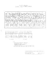
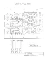
The 8' and 4' Flute filters are similar to the 16' Flute filter except that both of these sections
have additional components mounted on plug-in boards. These two plug-in boards are shown
on Drawing 130716 in the dotted border. The 8' and 4' Flute filters receive the signal from
the keyboard. The lower section below these signals become the Flute signal to be amplified
in TR-6 for the 8' Pre-Amplifier and TR-5 for the 4' Pre-Amplifier. Both of these stages
are properly biased to amplify the Flute signals before going into their respective Stop Switches
and Brightness Control M to be handled in transistor stages TR-8 and TR-9 the same as the
16' Flute signal.
In addition to the 8' and 4' Flute signal, these two filters also provide the signal for the String,
Brass and Reed tonal voices in the Combo Organ. The path of the signal will be described us -
ing the first signal groups of the 8' and 4' filter section. This signal from the 8' filter group
is coupled through components 146 and 144 to the input base of TR-1 Complex Pre-Amplifier.
It is also joined by a signal from the 4' Filter through components 70 and 71 . The signal is
mixed and amplified in TR-1 stage. The complex signal is then cpupled through a . 18 mfd (15)
capacitor from the collector of TR-1 to a load resistor 150 K (254). From across this load re
sistor a common lead is then wired to the three Stop Switches - String, Bass and Reed. The
sound level of these three stops can be set by the solo switch. This switch controls a 39 K re
sistor (3) across the normal 470 K (2) feed
b
ack resistor in the collector - base circuit of stage
TR-1. With the 39 K (3) resistor across the 470 K (2) greater feedback is provided to lower
the level of this stage. When the 39 K (3) is removed by the Solo Switch less feedback is provid
ed to assure a higher level of signal out of this stage. The string Stop Switch, when closed, will
take the complex signal from across the 150 K (254) load resistor and couple the signal through
numbered components 16 and 17 to the input base of TR -2. This stage is properly biased to
. amplify and also the circuit constants are chosen to provide a good string quality output signal.
This stage is refererd to as the active String Filter. The output of this stage TR -2, taken
from the collector through numbered components 130 and 31, is then wired to the junction of
items 118 and 112 before the signal is passed to the base of TR-8 through the 10 mfd capacitor
(112). Note, that this stage TR-8 receives all the signals described so far. The path of this
signal will follow the same pattern as the 16' Flute signal described previously.
When the Brass Stop is used, the signal is again taken from across the 100 K (254) resistor and
coupled to the base input of stage TR -3 through numbered components 42 and 43 . This stage is
properly biased to amplify the signal and also the circuit constants are chosen so that the output
signal is of good quality for a Brass sound. This is an active filter whose output is then coupled
through numbered components 51 and 60 to the same point as the output of the String filtered
signal. The signal is then handled in the pre-amplifier stage TR-8 the same as the 16' Flute
signal.
The Reed stop also takes the same complex signal from across the 150 K (254) load resistor and
will couple the signal into a passive filter consisting of numbered components 63, 62, 65, and 64
before joining the same input to the Pre-Amplifier stage TR-8.
The mixture IV signal is provided from the keyboard to the input base of stage TR -4 through num -
bered component 72. This stage is properly biased to amplify. The output of this stage taken from
the collector through components 87 and 86 will then be wired to the IV stop switch. The switch
handles the four di
f
ferent levels of signal the same as the 16' Flute Switch. The output of
the switch is then coupled to the common point going into the M (Brightness) switch . This is is -
Содержание 7300
Страница 2: ......
Страница 3: ...COMBO ORGAN Com i lr z Tran 13053 ...
Страница 4: ...Cable 12 lg 130577 6 lg 130578 EXPRESSION PEDAL 130558 Complete Rubber Bumper 130526 ...
Страница 14: ......
Страница 16: ......
Страница 18: ......
Страница 21: ......
Страница 22: ......


