


FLEXCOMM
II
C-5000 (Non-Digital)
Installation Manual
150-1355-000 Rev. M
CONFIDENTIAL AND PROPRIETARY TO COBHAM
Page 78
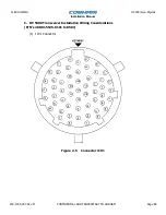
Pin(s) - Signal Name (Continued)
25 - RESERVED OUT SPARE B
Reserved spare output.
26 - VOICE AUDIO LO IN
Low side of the voice band receive audio that comes from the RT-5000. Use
shielded wire.
27 - RESERVED OUT SPARE A
Reserved spare output.
29 - AUDIO GND
Used for grounding shields. There is not separate digital and analog grounds
within the C-5000 so all shields can be connected to this pin. All shields should
also be connected to the Backshell of the connector and then grounded to the
aircraft frame.
30 - MIC HI OUT
High side of the transmit voice audio that connects to the RT-5000 input pin MIC
HI IN (pin Y). The pin along with MIC LO/PTT OUT should be connected using
shielded wire.
31 - UNSQUELCHED MAIN RECEIVE AUDIO IN
Single ended audio line that inputs unsquelched receiver audio from the RT-5000
Main Receiver into the C-5000. When the RT-5000 is using the external
encryption device at the C-5000, the main receiver audio from this input is
routed to the encryption device for decoding encrypted signals. It should be
connected inside a shielded cable to RT-5000 WIDE BAND MN RX AUDIO OUT
(pin q).
33 -
TX
This active low input pin holds the MIC LO/PTT OUT line low in order for external
devices to send a turn off message. No application for this pin is currently
available.
34 - IN SPARE #3
Spare input pin.
35 - ZEROIZE
This pin may either be pulled to ground or provide sw28 VDC cipher
erase, depending on internal jumper configuration
36 - IN SPARE #2
Spare input pin.


