FLEXCOMM
II
C-5000 (Non-Digital)
Installation Manual
150-1355-000 Rev. M
CONFIDENTIAL AND PROPRIETARY TO COBHAM
Page 77
Pin(s) - Signal Name (Continued)
14 - CIPHER /
PLAIN
Normally internally pulled high output pin able to sink 30mA to ground. Used to
set the mode of an external encryption device. Pins 14 and 16 provide for
control of devices that have different polarities for the mode set function. This
pin is not used in RT-5000 systems.
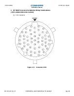
15, 32 - RT MIC HI / LO / PTT
This input will provide the primary voice band audio input.
16 - PLAIN /
CIPHER
Normally internally pulled high output pin able to sink 30mA to ground. Used to
set the mode of an external encryption device. Pins 16 and 14 provide for
control of devices that have different polarities for the mode set function. This
pin is not used in RT-5000 systems.
17 - TAKE CONTROL
If this input pin is grounded, the Serial control lines will be tri-stated. This allows
for control of the RT-5000 by another C-5000.
18 - EXTERNAL TRANSMIT AUDIO OUT
This output is a single ended audio output to the RT-5000 that carries wide band
audio to the RT-5000. Normally the audio on the pin comes from an external
encryption device connected to P500 of the C-5000 and is the encrypted transmit
audio from that device. Connect this pin in all installations even though an
external encryption box is not used. Use shielded wire.
19 - GROUND
General purpose ground. Not a required pin for installation.
20 - CONTROL GROUND
Provides for ground connection between the control head and the RT-5000.
This pin is very important to establish a common signal ground
between the units. It should be connected to RT-5000 pin D.
21- UNSQUELCHED GUARD RECEIVE AUDIO IN
Single ended audio line that routes unsquelched receiver audio from the RT-5000
Guard Receiver to the C-5000. When the RT-5000 is using the external
encryption device at the C-5000, the guard receiver audio from this input is
added inside the C-5000 to the decoded audio from the MAIN receiver so that
both MAIN and GUARD messages can be received simultaneously. It should be
connected inside a shielded cable to RT-5000 WIDE BAND GD RX AUDIO OUT
(pin w).
22 - +15 VDC
+15 VDC, 600 mA maximum - voltage is only available when the C-5000 is
powered on.


