background image

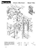
PARTS LIST

.

3

1


e

g

a

p


n

the schematic diagram


o

r

e

f

e

e

s

a

e

l

P

No.

No.

Description

Qty

Description

Qty

1

Phillips pan head screw  M4X14 
(with washer)

5

43 Left housing

1

2

Phillips pan head screw

1

44 Screw for tension spring

1

3

Spring for spindle lock

1

45 Spring washer

1

4

Gear box cover

1

46 Spindle lock cap

1

5

Circlip

1

47 Tension spring

1

6

Square-head bolts

2

48 Trigger

1

7

Deep groove ball bearing 698

1

49 Spindle lock spring

2

8

Big spiral bevel gear

1

50 Socket terminal 4.8X0.8

2

9

Steel ball S

φ

3

3

51 Switch

1

10 Primary gear shaft

1

52 Gear for connecting rod

1

11 Deep groove ball bearing 607-2Z

4

53 Deep groove ball bearing 609.2Z

1

12 Circlip for hole D19

2

54 Circlip for hole D24

1

13 Washer (7.1X

φ

13X0.5)

1

55 O ring

1

14 Intermediate shaft

1

56 Connecting sleeve

1

15 Big spiral bevel gear

1

57 Stator

1

16 Circlip for shaft D9

2

58 Deep groove ball bearing 608-2Z

1

17 Circlip for shaft D8

1

59 Rotor

1

18 Pinion

1

60 Socket terminal 2.8X0.8

2

19 Separation sleeve

1

61 Self-tapping screw ST2.9X10

2

20 Circlip for hole D20

2

62 Lower carbon brush holder

1

21 Deep groove ball bearing 699

1

63 Carbon brush

2

22 Pipe joint C

1

64 Deep groove ball bearing 606.2Z

1

23 Bellows

1

65 Bearing sleeve

1

24 Pipe joint D

1

66 Upper carbon brush holder

1

25 Self-tapping screw ST4.2X14

6

67 Self-tapping screw ST4.2X16

9

26 Gear box

1

68 Right housing

1

27 Dust cover

2

69 Right label

1

28 Spindle (120V)

1

70 Power cord sleeve

1

29 Fixed guard

1

71 Hex key 5

1

30 Phillips pan head screw (with

washer)

2

72 Power cord

1

31 Cross-shaped screw M4X12

1

73 Circlip for shaft D10

2

32 Rubber block

1

74 Depth lever

2

33 Screw for rubber block M5

1

75 Locking lever

2

34 Moving guard

1

76 Washer

1

35 Baffle ring

1

77 Hexagon  socket  head  cap  screws 

M6X12

1

36 Inner flange

1

78 Edge guide locking spring

1

37 TCT blade

1

79 Base plate

1

38 Blade screw

1

80 Cylindrical spring pin D6X35

1

39 Outer flange (120V)

1

81 Parallel guide

1

40 Self-tapping screw ST4.2X12

1

82 Power cord clamp

1

41 Moving guard lever

1

83 Wire connecting blocks

1

42 Left label

1

ENGLISH

14

Содержание 68125169

Страница 1: ...procedures and the warranty Keep it and the original sales invoice in a safe dry place for future reference Questions 1 866 206 0888 Notre personnel du service la client le est disponible pour vous a...

Страница 2: ...ccidents b Ne pas utiliser d outils lectriques dans des atmosph res explosives comme en pr sence de liquides de gaz ou de poussi res in ammables Les outils lectriques cr ent des tincelles qui peuvent...

Страница 3: ...ool Such preventive safety measures reduce the risk of starting the tools accid e Store idle tools out of reach of children and other untrained Tools are dangerous in the hands of untrained users f Ma...

Страница 4: ...ame ne peut pas vous prot ger de la lame sous le travail Ne pas faire fonctionner la scie si le prot ge lame inf rieur ne bouge pas librement ou ne se ferme pas instantan ment Ne jamais pincer ou atta...

Страница 5: ...ndir vers l arri re vers l utilisateur L effet de rebond est le r sultat d une mauvaise utilisation de l outil ou de proc dures ou conditions de fonctionnement incorrectes et peut tre vit en prenant l...

Страница 6: ...LE DES COMPOSANTS A Lame de scie K Prot ge lame inf rieur B Interrupteur L Plaque de base C Bouton de verrouillage M Rangement pour cl hexagonale D Prot ge lame sup rieur N Bouton de verrouillagedel a...

Страница 7: ...ir le prot ge lame inf rieur K en d pla ant le levier de guide prot ge lame inf rieur J Retirerla lame N S assurer que la nouvelle lame est bien centr e sur la bride int rieure lors du montage de la l...

Страница 8: ...Avant d effectuer tout r glage s assurer que la fiche est retir e de la prise Desserrer la vis de r glage de profondeur l aide du levier de blocage de la profondeur O Tenir la plaque de base plat cont...

Страница 9: ...rale Marquer une ligne de coupe sur la pi ce couper U D poser la partie avant de la plaque de base L plat sur la surface de la pi ce couper en s assurant que la lame ne touche pas la pi ce Mettre l ou...

Страница 10: ...urs de coupe Rel cher le prot ge lame inf rieur lorsque la lame commence couper Lorsque la semelle est plat sur la surface en cours de coupe proc der la coupe en direction avant jusqu la fin de la cou...

Страница 11: ...de l utiliser et le faire r parer Nettoyer l outil avec un chiffon humide et un d tergent doux Ne pas utiliser de solvants car ils endommagent les pi ces en plastique et les font craquer Remplacement...

Страница 12: ...otaraudeuse ST2 9 10 2 20 Anneau de retenue pour trou D20 2 62 Porte balaien carbone inf rieur 1 21 Roulement billes gorges profondes 699 1 63 Balai en carbone 2 22 Joint de tuyaux C 1 64 Roulement bi...

Страница 13: ...FRAN AIS ENGLISH AVERTISSEMENT Les r parations doivent tre faites par un centre de services autoris Ne pas ouvrir ou d monter cet outil lectrique WARNING Repairs should be made by an authorized repair...

Страница 14: ...inion 1 60 Socket terminal 2 8X0 8 2 19 Separation sleeve 1 61 Self tapping screw ST2 9X10 2 20 Circlip for hole D20 2 62 Lower carbon brush holder 1 21 Deep groove ball bearing 699 1 63 Carbon brush...

Страница 15: ...ct with grounded surfaces such as pipes radiators ranges and refrigerators There is an increased risk of electric shock if your body is grounded c Do not expose power tools to rain or wet conditions W...

Страница 16: ...control g Check for misalignment or binding of moving parts breakage of parts and any other condition that may affect the tool s operation If damaged have the tools serviced before using Many accident...

Страница 17: ...tracting handle and make sure it moves freely and does not touch the blade or any other part for all angles and depths of cut 3 Check the operation and condition of the lower guard spring If the guard...

Страница 18: ...upports must be placed under the panel on both sides near the line of cut and near the edge of the panel Do not use a dull or damaged blade Unsharpened or improperly set blades produce narrow kerf cau...

Страница 19: ...this manual carefully and understand all the content prior to assembly and operation CAUTION Always ensure that the tool is switched off and unplugged from the main power supply before assembly Changi...

Страница 20: ...the parallel guide lock screw F to secure it into position Ensure that the parallel guide rests are parallel to the base plate to ensure a straight parallel cut Switching on and off NOTE Before engag...

Страница 21: ...socket Loosen the angle locking lever E Adjust the base plate L to the desired angle between 0 and 45 The adjusted cutting angle can be verified on the angle scale T Retighten the angle locking lever...

Страница 22: ...h full speed and then reentering the cut slowly When cutting across the grain the fibers of the wood will have a tendency to lift and tear Movethe saw slowly to minimize this effect NOTE For best cutt...

Страница 23: ...e blade to come to a full stop before removing it from the cut Never pull the saw backward since the blade will climb out of the cut and kickback may occur Turn the saw around and finish the cut in a...

Страница 24: ...hese products have been made to demanding high quality standards and are guaranteed for domestic use against manufacturing faults for a period of 24 months from the date of purchase This guarantee doe...

Отзывы: