Electrical connection
Worcester Commercial Boiler Series – 6720814332 (2019/04)
30
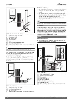
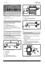
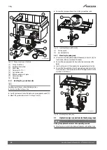
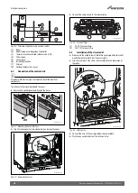
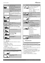
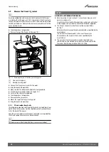
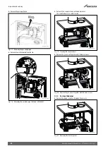
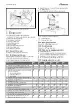
Fig. 57 Connecting the outside temperature sensor
6.8
Connecting a cylinder temperature sensor
Connection to the grey connector block is not possible.
6.9
Connecting the 3-way valve
Connection to the turquoise connector block is not possible.
6.10
Connecting the function module (accessory)
For the assembly and combination options of the function modules, refer
to the relevant installation instructions of the function modules.
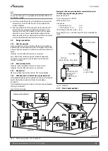
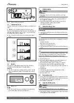
▶ Connect the BUS cable to the connection for the modulating
controller (
chapter 6.5).
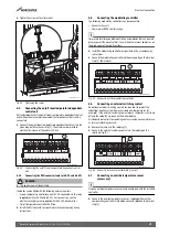
▶ Connect the power supply of the function module to the connector
block [1]. Use the power cable supplied with the function module for
this.
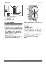
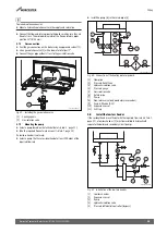
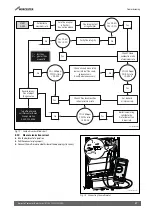
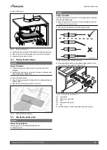
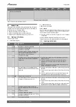
Fig. 58 Connecting the mains voltage
6.11
Connecting the cylinder primary pump
Connection to the grey pump connector block is not possible.
6.12
Connecting the hot water circulation pump
Connection to the purple connector block is not possible.
6.13
Connecting the pump
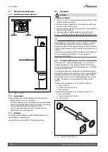
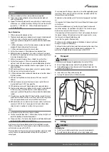
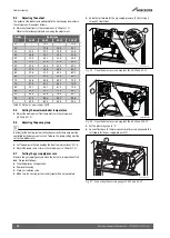
With pump group:
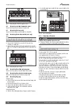
▶ Connect the control signal wire from the pump to the white plug of the
terminal strip [1].
▶ Remove the green plug [2] from the terminal strip.
▶ Connect the pump's power cable to the terminal strip [2].
▶ Fasten both cables using the strain relief devices mounted
beforehand on the cables.
Without pump group:
▶ Slide the strain relief (provided) over the power cable of the pump.
▶ Connect the pump's power cable to the green connector block on the
terminal strip [2].
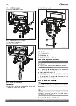
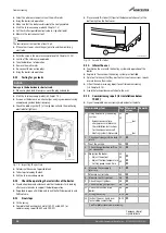
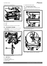
Fig. 59 Connection of pump
6.14
Connecting to the mains
DANGER:
Danger of fatal accident due to electric shock.
▶ Disconnect the boiler from the mains power supply before working
on the boiler. Guard against unintentional re-connection.
All Worcester boilers require a permanent live.
A mains supply of 230 V - 50 Hz is required.
External controls are suitable for volt free installation (or 230V via the
relay supplied with the 50-V2 and 65-V2 boilers).
Wiring to the boiler must be in accordance with the current I.E.E.
(BS 7671) Wiring Regulations and any local regulations.
Wiring should be a 3 core PVC insulated cable, not less than 0.75 mm
2
(24 x 0.2 mm), and to table 15 of BS 6500.
Connection must be made in a way that allows complete isolation of the
electrical supply such as a double pole switch having 3 mm contact
separation in both poles, or by a three pin connector, serving only the
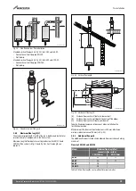
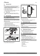
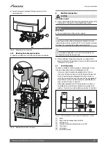
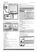
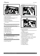
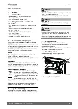
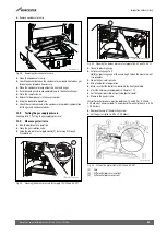
boiler and system controls. This boiler is equipped with a double pole
switch [1]. The means of isolation must be accessible to the user after
installation.
The electrical connection to the mains supply should be readily
accessible and adjacent to the boiler.
If the supply cord is damaged, it must be replaced by a qualified
electrician to avoid a hazard and must be an original spare part.
The electrical supply for both the boiler and the system must be taken
from the same fused spur outlet.
0010010013-001
13 12 11 10 9 8 7 6 5 4 3 2 1
1
0010010018-001
11
L
PE
N
0010010022-001
2
11

