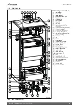
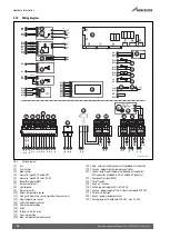
Pre-Installation
19
Worcester Commercial Boiler Series – 6720814332 (2019/04)
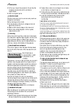
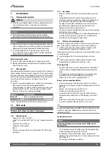
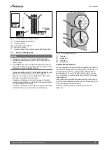
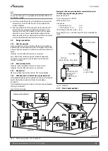
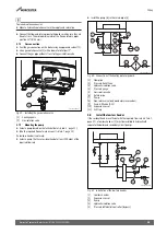
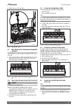
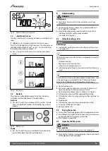
Fig. 23 Side flue and rear flue installation
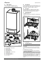
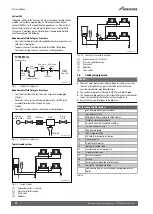
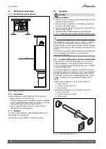
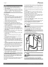
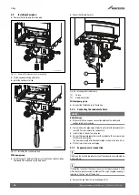
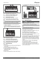
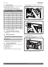
Standard vertical flue pack (
fig. 24) for 50-V2 and 65-V2:
• Concentric vertical flue pipe 80/125;
• Wall clamp.
Standard vertical flue pack (
fig. 24) for 85-V2 and 100-V2:
• Concentric vertical flue pipe 100/150;
• Wall clamp.
Fig. 24 Standard vertical flue pack
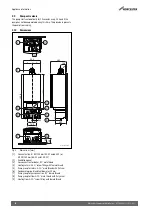
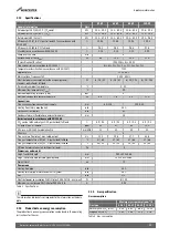
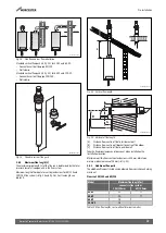
3.8.2
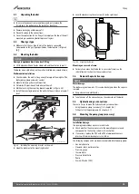
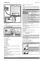
Maximum Flue length (L)
The maximum pipe length (L) of the flue run is determined by the total
pressure loss of all components in the flue system.
Maximum length of horizontal or vertical extensions for 80/125 and
100/150 flue system (
fig. 25 and fig. 26). For flue length see
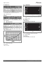
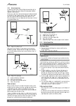
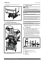
Fig. 25 Vertical flue length
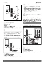
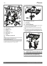
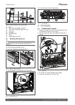
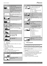
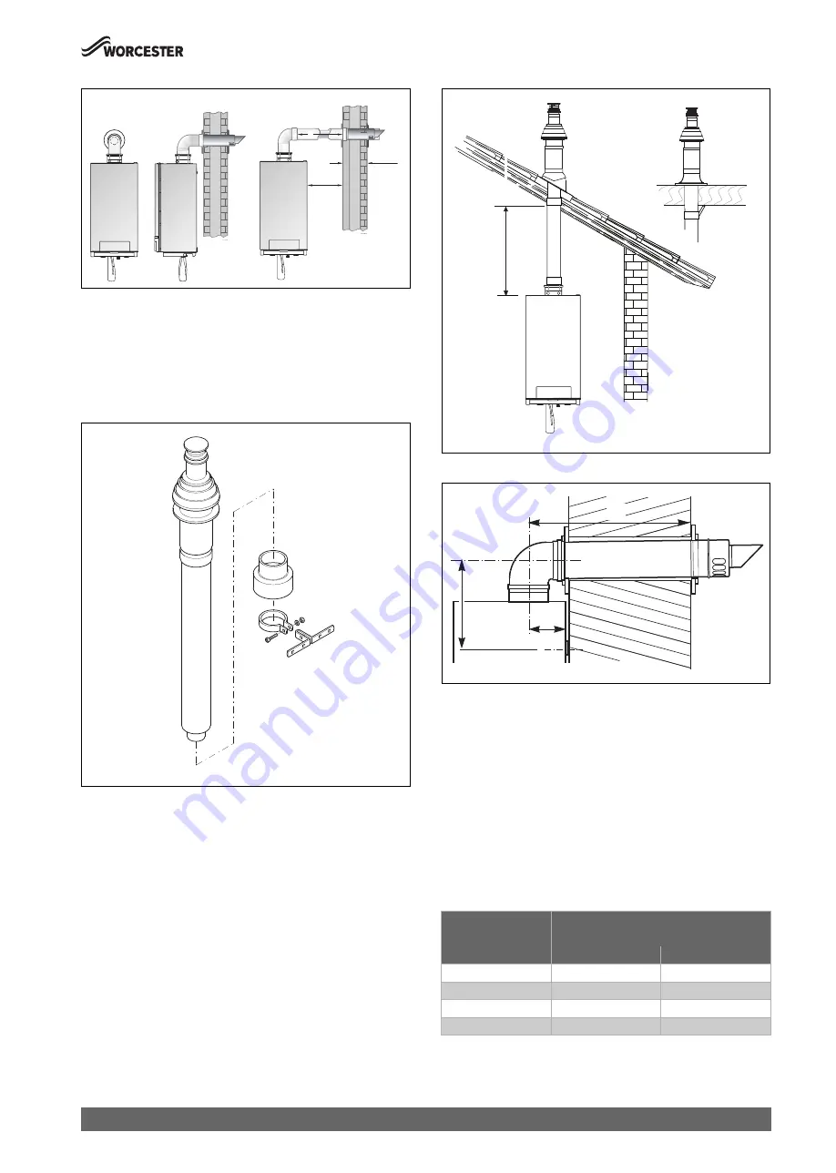
Fig. 26 Horizontal flue length
[A]
Distance from centre of flue to inside rear wall
[B]
Distance from centre wall bracket to centre of flue elbow
[L]
Distance from centre of flue to outside wall
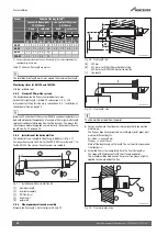
Take the flue pipe clearances into account when installation the
linstallation location.
Maximum wall thickness without extensions is 415mm. Maintain a
minimum side clearance of 25mm (
3.8.3
Additional flue parts
The additional flue parts listed can be ordered from your chosen heating
merchant.
Flue size 100/150 and 80/125
Table 10 Max. flue lengths, incl. wall/roofterminal in metres
0010025995-001
415 mm
25 mm
L
0010025996-001
Model
Maximum flue length [m]
concentric flue system
100/150mm
80/125mm
50-V2
20
7.7
65-V2
20
7.7
85-V2
18
-
100-V2
18
-
0010025997-001
L
0010025998-001
A
L
B


