20
Owner Service
MAN1248 (2/26/2018)
Gearbox
Each Woods gearbox is equipped with tapered bear
-
ings throughout. These bearings are preset at the fac
-
tory and normally do not require adjustment during
their useful life. Gearbox must be half full of SAE 90
gear lube. Check every eight hours. If there are any
leaks around bolts or covers, apply #3 Permatex
®
or
Gasket Compound to seal. Check seals to be sure they
do not leak.
Hydraulic Drive Oil Recommendations
Use of type "A" or "F" automatic transmission fluid is
recommended for all ambient temperatures; however,
the following motor oils may be used:
SAE 30-30W for temperatures above 90°F
SAE 20-20W for 35° to 90°F
SAE 10-10W for temperatures below 35°F
Oil level should be checked daily and oil added as nec
-
essary to maintain level at full mark on dipstick. Capac
-
ity is 35 gallons.
Oil Leaks
Keep hands and body away from pressurized
lines. Use paper or cardboard, not hands or other
body parts to check for leaks. Wear safety goggles.
Hydraulic fluid under pressure can easily penetrate
skin and will cause serious injury or death.
Make sure that all operating and service person
-
nel know that if hydraulic fluid penetrates skin, it
must be surgically removed as soon as possible by
a doctor familiar with this form of injury or gan
-
grene, serious injury, or death will result.
CONTACT A PHYSICIAN IMMEDIATELY IF FLUID
ENTERS SKIN OR EYES. DO NOT DELAY.
Most oil leaks occur in the tubes, hoses and fittings. If
you have an oil leak, check where the leak is and fix it.
Three types of fittings are used on this machine:
●
O-Ring seal fittings on pumps, motors, etc. - A leak
here is usually from a faulty O-ring.
●
Pipe fittings - Use Teflon
®
tape to seal these
"thread seal" joints.
●
Hose, hose nipple, and clamp fitting - Surfaces
should be in good condition. Hoses should be of
correct size and clamps tightened.
BLADE SERVICING
■
Do not handle blades with bare hands. Care
-
less or improper handling may result in serious
injury.
Raise cutter head and lock in up position. Inspect
blades before each use to determine that they are
properly installed and in good condition. Check to be
sure blades are snug but still swivel on blade pin (see
Blade Installation). Replace any blade that is bent,
excessively nicked, worn or has any other damage.
Small nicks can be ground out when sharpening.
Blade Removal
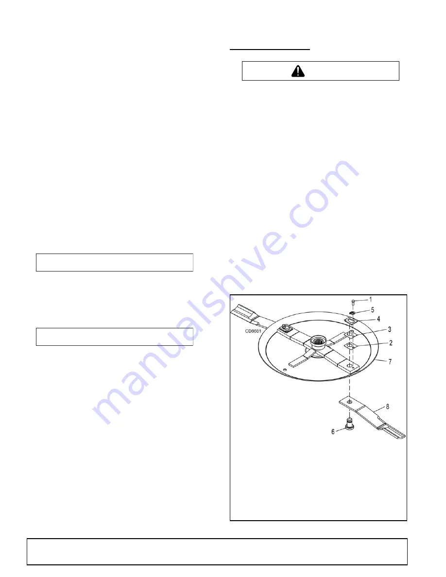
(Figure 4)
Align crossbar and blade pin assembly with blade
access hole in cutter frame. Remove bolt (1) and blade
pin lock clip (5). Slide keyhole plate (4) out of blade pin
groove and remove. Remove spacers and drive pin out
of crossbar.
NOTICE
■
If blade is seized in crossbar and extreme
force will be required to remove it, support cross
-
bar from below to prevent gearbox damage.
Figure 4
. Blade Removal/Installation
A
WARNING
A
WARNING
CAUTION
1. 1/2 NC x 1-1/4 HHCS GR5
2. Shim, 18 ga
3. Shim, 20 ga
4. Keyhole plate
5. Blade pin lock clip
6. Blade pin
7. Crossbar
8. Blade
Содержание DBH5.30
Страница 1: ...OPERATOR S MANUAL DITCH BANK ROTARY CUTTER MAN1248 Rev 2 26 2018 DBH5 31 DBH5 31Q DBH6 31 DBH6 31Q...
Страница 23: ...Trouble Shooting 23 MAN1248 2 26 2018 TROUBLE SHOOTING HYDRAULIC CIRCUIT SCEMATIC...
Страница 44: ...44 Parts MAN1248 2 26 2018 MAIN FRAME ASSEMBLY...
Страница 46: ...46 Parts MAN1248 2 26 2018 CUTTER SECTION ASSEMBLY...
Страница 57: ...Parts 57 MAN1248 2 26 2018 NOTES...


