Wood-mizer 1992 LT30HD Скачать руководство пользователя страница 54

Setup & Operation

Blade Height Sight Gauge

2

2-26

HD92doc042701

Setup & Operation

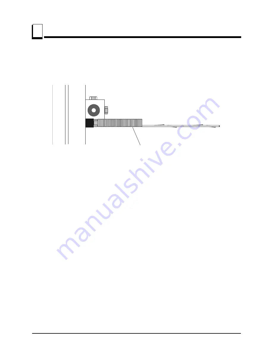
2.17 Blade Height Sight Gauge

See Figure 2-16. The sight gauge is provided on the cutting head carriage to help you
decide where to make the first cuts on a log.

Move the carriage forward until the blade is close to the end of the log.

Position yourself so that your eyes are level with the bottom of the sight gauge spring.
With one eye closed, move your head up or down until the bottom of the sight gauge is
lined up with the bottom of the blade.

Sight down the length of the log. You should be able to see where the blade will pass
through the log down its entire length. Raise or lower the cutting head until you get the
blade height you want.

HINT: After judging by eye where you want to make your first slab cut, check the scale.
Move the up/down crank to fine-tune the blade height to an even measurement on the
blade height scale.

Example: Adjust the blade up to 15" rather than cut at 14 13/16". This will make adjust-
ments for the next cuts easier to figure on the scale.

FIG. 2-16

Sight gauge eye-level

with bottom of blade

SM0047

Содержание 1992 LT30HD

Страница 1: ...eration Maintenance Manual 1992 LT30HD rev C7 F7 1992 LT40HD rev C7 F7 Safety is our 1 concern Read and understand all safety information and instructions before operating set ting up or maintaining t...

Страница 2: ...he continental U S call our toll free Parts hotline at 1 800 448 7881 Please have the vehicle identification number and your customer number ready when you call Wood Mizer will accept these methods of...

Страница 3: ...dule you for a service call Office Hours All times are Eastern Standard Time Please remember that Indiana does not go on Day light Savings Time in the summer Monday Friday8 a m to 5 p m Saturday8 a m...

Страница 4: ...icates the model is approved for sale in countries that have adopted German Gerpr fte Sicherheit G S safety standards The model number is located on the middle blade housing cover See the figure at th...

Страница 5: ...v HD92doc042701 V I N DESCRIPTION MODEL NUMBER DESCRIPTION...

Страница 6: ......

Страница 7: ...1 Stationary Sawmill Setup 2 1 2 2 Portable Sawmill Setup 2 2 2 3 Preparing The Sawmill For Operation 2 5 2 4 Replacing The Blade 2 6 2 5 Tensioning The Blade 2 7 2 6 Tracking The Blade 2 8 2 7 Starti...

Страница 8: ...Belts 3 11 3 12 Brake Strap Adjustment 3 12 3 13 Hydraulic System 3 14 3 14 Drive Bearing 3 16 3 15 Up Down System 3 17 3 16 Power Feed 3 20 3 17 Miscellaneous Maintenance 3 22 SECTION 4 TROUBLESHOOT...

Страница 9: ...e Guide Arm Vertical Adjustment 5 11 5 8 Blade Guide Arm Horizontal Adjustment 5 12 5 9 Aligning The Blade Guides 5 14 5 10 Blade Deflection 5 15 5 11 Blade Guide Vertical Tilt Adjustment 5 16 5 12 Bl...

Страница 10: ......

Страница 11: ...ns before operating this equipment and observe all safety warn ings Safety instructions are listed in this section by the following operations Blade Handling Sawmill Setup Sawmill Operation 1 1 Blade...

Страница 12: ...ion before turning the key switch to the ON or ACC position This prevents unwanted carriage movement DANGER Check to be sure the saw head is resting firmly on the rest pin and mast rail stops and that...

Страница 13: ...he cutting head is moved far enough forward so the log does not hit it CAUTION Failure to fully extend the log clamp before tow ing can result in damage to the clamping assembly during towing IMPORTAN...

Страница 14: ...ngine Drive Belt 2BX682 P12139 2 15hp Electric Motor Drive Belt 2BX702 P04857 2 Alternator Belt G24 A33 P11542 Alternator Belt D20 E15 A30 P11628 Blade Pulley Belts B571 P04185 Power Feed Drive Belt 4...

Страница 15: ...nd tooth set specifications Gas Diesel Engine Size Recommended Blade For Sawing Softwood Hardwood Frozen or Hard to Cut Wood 5 hp 14hp 042 x 7 8 x 1 1 4 035 x 7 8 x 1 1 4 045 x 7 8 x 1 1 4 F 1 1 TRU S...

Страница 16: ...c mill is 4400 lbs 1996 Kg Max Length 1 LT30HD 36 91 5 cm 2 2 Maximum diameter capacity prior to revision C8 is 32 16 8 5 1 m LT40HD 36 91 5 cm 2 21 6 4 m LT30HD with Optional 12 Bed Extension 3 3 Log...

Страница 17: ...on HD92doc042701 1 7 1 1 7 Engine Motor Specifications See Table 1 5 The power options available for the LT30HD and LT40HD sawmills are listed below Engine Motor Type Manufacturer Model Number 24HP Ga...

Страница 18: ...7 The overall dimensions of the LT40HD sawmill are listed below LT30HD LT30HD with Surge Brake Trailer Pkg Length 19 11 5 3 m 21 9 6 6 m Width 8 2 4 m 8 2 2 5 m Height 7 6 2 3 m 7 6 2 3 m Weight 2433...

Страница 19: ...the Wood Mizer LT30HD LT40HD are shown below FIG 1 1 Trailer Hitch Operator Seat Option Control Box Water Lube Engine Drive Assembly Outer Blade Guide Arm Blade Tensioner Hydraulic Log Clamp Hydrauli...

Страница 20: ...Safety General Information Hydraulic Schematic 1 1 10 HD92doc042701 Safety General Information 1 10 Hydraulic Schematic FIG 1 2 HYDRAULIC SCHEMATIC REVISIONS E7...

Страница 21: ...Safety General Information Hydraulic Schematic Safety General Information HD92doc042701 1 11 1 FIG 1 3 HYDRAULIC SCHEMATIC REVISIONS C7 E6...

Страница 22: ...rch Can P09128 2 Hydraulic Cylinder 3 Bore X 8 Stroke Rev E7 F4 C5 P12845 J D Hydraulic P12845 3 3 Welded cylinder P12845 replaces tie rod cylinder P09125 originally supplied before Rev F5 Hydraulic C...

Страница 23: ...e C7 P12847 J D Hydraulic P12847 3 3 Welded cylinder P12847 replaces tie rod cylinder P09128 originally supplied Hydraulic Cylinder 3 Bore X 8 Stroke CV1 A11687 Wood Mizer A11687 Check Valve CV2 A1168...

Страница 24: ...4 Hose 1 4 X 142 Hydraulic W Fittings White Clamp Cylinder Top LT40HD P12548 Hose 1 4 X 164 Hydraulic W Fittings H8 Dark Orange Clamp Cylinder Base LT30HD P12543 Hose 1 4 X 135 Hydraulic W Fittings Da...

Страница 25: ...ydraulic W Fittings Blue Loading Arm Cylinder Top LT40HD P12549 Hose 1 4 X 173 Hydraulic W Fittings H16 Red Loading Arm Cylinder Bottom LT30HD P12545 Hose 1 4 X 151 Hydraulic W Fittings Red Loading Ar...

Страница 26: ...Hose 1 4 X 173 Hydraulic W Fittings H7 White Clamp Cylinder Top LT30HD P12544 Hose 1 4 X 142 Hydraulic W Fittings White Clamp Cylinder Top LT40HD P12548 Hose 1 4 X 164 Hydraulic W Fittings H8 Orange...

Страница 27: ...W Fittings Blue Loading Arm Cylinder Top LT40HD P12549 Hose 1 4 X 173 Hydraulic W Fittings H16 Red Loading Arm Cylinder Bottom LT30HD P12545 Hose 1 4 X 151 Hydraulic W Fittings Red Loading Arm Cylind...

Страница 28: ......

Страница 29: ...reep after prolonged use NOTE Make sure the unit is level before securing It IS possible to twist the mill frame by jacking one foot higher than the others DANGER Do not operate a stationary sawmill w...

Страница 30: ...using the jack handle Pull the locking pin to release the outrigger and lower the outrigger as necessary Secure with the locking pin DANGER Put front outrigger down before moving cutting head from th...

Страница 31: ...ut the engine running will result in power drainage from the battery 5 Use the carriage fwd rev switch left side of control box to move the cutting head toward the front end of the mill The hydraulic...

Страница 32: ...the entire outrigger to remove the sawmill weight from it and adjust the outrigger base as necessary Lower the entire out rigger and use the locking pin to secure in position CAUTION Do not adjust the...

Страница 33: ...e Remove the six locking pins and two hold down nuts Unplug the tail light board from the auxiliary adapter Remove all four sections of the perimeter fence Adjust the jockey wheel down by turning the...

Страница 34: ...l the wheel is pulled in and the blade is lying loose in the blade housing Lift the blade out of the blade housing When installing a blade make sure the teeth are pointing the correct direction The te...

Страница 35: ...trol or while cutting Ambient temperature changes will cause tension to change Adjust the ten sion handle as necessary to maintain the recommended tension level CAUTION The blade tension should be rel...

Страница 36: ...mm out from the edge of the blade wheel 1 32 75 mm Position 1 1 2 blades so the gullet is 3 16 4 5 mm out from the edge of the blade wheel 1 32 75 mm To adjust where the blade travels on the blade wh...

Страница 37: ...ace the covers DANGER Never operate the sawmill without all guards and covers in place and secured Be sure the blade housing and pulley covers are in place and secure If applicable use the safety reta...

Страница 38: ...d pulley covers are in place and secure before starting the sawmill If applicable use the safety retainer pin and cable to fasten blade housing cov ers DANGER Do not start the engine or motor when the...

Страница 39: ...Operation HD92doc042701 2 11 2 2 8 Hydraulic Control Operation Revisions E7 See Figure 2 7 Use the five control levers to do the following steps This gets the mill ready to load a log FIG 2 7 Rear Toe...

Страница 40: ...le operating the sawmill Leave loading arm halfway up while log is on sawmill bed 1 Lower the clamp lever to move the log clamp toward the loading side of the mill Be sure the clamp is in the down pos...

Страница 41: ...t braces will begin to lower Release the turner lever after the turner arm is lowered but before the side supports begin to lower This stops the log being loaded from damaging the turner and or fallin...

Страница 42: ...by lifting the rear toe board lever up Once a flat has been made and the log is ready to be turned push the appropriate toe board lever down to lower either toe board until it falls below the level o...

Страница 43: ...ing equip ment to move the logs to the foot of the loading arms 2 Roll the log onto the loader so that it is approximately centered with the sawmill bed The log turner will operate much easier if the...

Страница 44: ...log against the side supports 5 Lower the turner lever to lower the turner arm below the log 6 Raise the turner arm to get a new bite on the log 7 Disengage the clamp 8 The log can be turned now Repea...

Страница 45: ...ed Revisions E7 Raise the appropriate lever to raise the front or rear toe board until the heart of the log measures the same distance from the bed rails at each end of the log Revisions C7 E6 Raise t...

Страница 46: ...2 include a retaining pin which allows the clamp to be stored on the clamp tube end plate See Figure 2 11 Remove the retaining pin and clamp extension from its storage position at the end of the clamp...

Страница 47: ...h the switch down to lower the cutting head Hold the switch in position until the cutting head reaches the desired height then release The up down switch is designed to return to the neutral or off po...

Страница 48: ...less than 1 25 4 mm 2 Use the blade guide toggle switch on the control panel to adjust the outer blade guide as necessary Push the switch to the left to move the arm in Push the switch to the right t...

Страница 49: ...the safety retainer pin and cable to fasten blade housing covers See Figure 2 14 The clutch brake lever is located next to the engine 4 To engage the blade pull the lever down until it locks in the d...

Страница 50: ...direction in which the carriage travels Turn the fwd rev switch upward to the CARRIAGE FWD position to move the car riage forward Turn the switch down to the CARRIAGE REV position to move the carriag...

Страница 51: ...lever UP to stop the blade and drop the engine to idle Remove the board from the top of the log CAUTION Be sure to stop the blade when returning the carriage This will not only prevent the blade from...

Страница 52: ...he log slow down the feed rate When the teeth exit the end of the log turn the feed rate all the way down and disengage the clutch brake lever Remove the slab that you have just cut from the log 7 Use...

Страница 53: ...ide supports halfway up the flitch height Wider flitches should be placed to the clamp side When they are edged flip them over to edge the sec ond side without disturbing the other flitches or without...

Страница 54: ...the bottom of the sight gauge is lined up with the bottom of the blade Sight down the length of the log You should be able to see where the blade will pass through the log down its entire length Raise...

Страница 55: ...cator is attached to the frame and moves up and down with the car riage head A retrofit is available so that the indicator remains at eye level and the scales move up and down Rev D3 The scales are at...

Страница 56: ...want to cut 1 25 mm random width boards from a log Use the sight gauge to position the blade for the first cut Move the carriage to an even measurement on the inch scale Make a trim cut Return the car...

Страница 57: ...e indicator with the nearest mark on the scale you want to use Make a trim cut When you return the carriage for a second cut lower the carriage to the next mark on the scale This mark shows where the...

Страница 58: ...2 gallons 3 8 7 6 liters per hour A squirt of liquid dishwashing detergent in the water bottle will help clean the blade when cutting wood with a high sap content WARNING Never use flammable fuels or...

Страница 59: ...Failure to fully extend the log clamp before tow ing can result in damage to the clamping assembly during towing 3 Use the hydraulic controls to raise the log turner and loader as high as they will g...

Страница 60: ...ocated from the rest pin 8 If necessary adjust the two stops located at the bottom of the mast so the saw head con tacts them after it is lowered 3 4 19mm past where it contacts the rest pin See Figur...

Страница 61: ...r tires Raise all but the very front outrigger DANGER Check to be sure the saw head is resting firmly on the rest pin and mast rail stops and that the safety chain is secured before towing the sawmill...

Страница 62: ......

Страница 63: ...ar Life See Table 3 1 This chart lists estimated life expectancy of common replacement parts if proper maintenance and operation procedures are followed Due to the many variables which exist during sa...

Страница 64: ...s 2 Check the rollers for performance and wear every blade change Make sure the rollers are clean and spinning freely If not rebuild them Replace any rollers which have worn smooth or have become cone...

Страница 65: ...Loader Maintenance HD92doc042701 3 3 3 3 3 Hydraulic Log Loader Remove all sawdust and debris from around the velocity fuse valves every 8 hours of operation The valves are located at the bottom of t...

Страница 66: ...ade change See Figure 3 2 2 Make sure the blade screw or cam bearing on machines before 11 91 in the top center of the C frame is 1 16 1 5 mm below the bottom of the blade If not loosen the nut and ad...

Страница 67: ...ngs Loosen the thumb screws on the upper cam housing covers and open Brush any sawdust buildup from the housings 3 Check the track scrapers as needed Make sure the scrapers fit firmly against the rail...

Страница 68: ...ce Track Rollers 3 3 6 HD92doc042701 Maintenance 3 6 Track Rollers See Figure 3 4 1 Lubricate the greasable track roller bearings every fifty hours of operation Use a NLGI No 2 grade lithium grease FI...

Страница 69: ...and lubricate the vertical mast rails every 50 hours of operation Clean with solvent and remove any rust with a light grade sand paper or emery cloth Lubricate the mast with motor oil or automatic tra...

Страница 70: ...Mizer Remove the control panel cover Use a cotton swab to apply grease to the switch contact ends WARNING Drum switch grease contains Petroleum Hydro carbon Lubricant Eye and skin irritant If introduc...

Страница 71: ...the blade guide arm every fifty hours of operation to help prevent it from rusting 2 Grease the clamp mechanism loading arm and side supports with a NLGI No 2 grade lithium grease every fifty hours of...

Страница 72: ...de Tensioner 1 Lubricate the chrome rods of the tensioner system with a heavy duty teflon spray lubri cant such as Gunk L508 every fifty hours of operation 2 Lubricate the tensioner screw handle with...

Страница 73: ...Rotate the blade wheel belts and check them for wear Rotating the belts every 50 hours will give you longer belt life Replace belts as necessary Use only B57 belts manufac tured by Goodyear or Brownin...

Страница 74: ...Loosen the two brake strap clamping bolts and slide the lower brake strap clamping plate and metal backed brake strap forward until snug Retighten the bolts Replace the belt cover Hydraulic Sawmills R...

Страница 75: ...Maintenance Brake Strap Adjustment Maintenance HD92doc042701 3 13 3 See Figure 3 6 FIG 3 6 Metal backed brake strap Brake strap clamping bolts 2 Lower clamping plate SM0056B...

Страница 76: ...as Exxon Univis J26 For alternate fluids and or other temperature ranges refer to the chart below Operating above the recommended temper ature range of a fluid could result in excessive pump wear Oper...

Страница 77: ...e pump Lay a 6 15 cm straightedge across the shaft s exposed bearing journal so it is in contact with the end of the stator s outer wrap Measure the gap between the straightedge and the fiber thrust w...

Страница 78: ...aring housing every 1000 hours of operation Remove the top and bottom oil plugs Pour an Automatic Transmission Fluid ATF such as Dexron III ATF into the top hole until it begins to flow from the botto...

Страница 79: ...Up Down System Maintenance HD92doc042701 3 17 3 3 15 Up Down System 1 Grease the up down gear reducer shaft bearing with a NLGI No 2 grade lithium grease every 1000 hours of operation See Figure 3 9 F...

Страница 80: ...housing cover To tighten the belt loosen the two motor mount nuts Adjust the bolt underneath the motor upward so there is 3 8 9 5 mm deflection with a 7 lb 3 2 Kg deflection force Tighten the jam nut...

Страница 81: ...DANGER Always secure the cutting head with a 5 16 chain with at least 1900 lbs working load capacity before adjusting the up down chain The cutting head may fall causing severe injury or death CAUTIO...

Страница 82: ...large feed pulley Tighten the belt so there is 1 8 3 mm deflection with a 7 lb 3 2 Kg deflec tion force Retighten the motor bolts and replace the feed motor cover 2 Adjust the power feed chain as need...

Страница 83: ...Maintenance Power Feed Maintenance HD92doc042701 3 21 3 See Figure 3 13 FIG 3 13 Feed Chain Adjustment Nuts 3H0018B...

Страница 84: ...ny damaged or unreadable decals immediately Order decals from your Customer Service Representative WARNING Keep all safety warning decals clean and visi ble If decal becomes worn or damaged replace im...

Страница 85: ...Excess Sawdust From Blade Wheel Housings And Sawdust Chute SEE SECTION 3 4 Check Blade Screw or cam bearing SEE SECTION 3 4 EVERY 8 HOURS Clean And Lubricate Track SEE SECTION 3 5 Remove Sawdust From...

Страница 86: ......

Страница 87: ...ns See Section 3 9 See Section 3 15 See Section 3 16 Check belt tensions See Section 3 15 See Section 3 16 Check brake strap tension See Section 3 12 Rotate drive idle blade wheel belts Check all belt...

Страница 88: ...ins See Section 3 9 See Section 3 15 See Section 3 16 Check belt tensions See Section 3 15 See Section 3 16 Check brake strap tension See Section 3 12 Rotate drive idle blade wheel belts Check all bel...

Страница 89: ...chains See Section 3 9 See Section 3 15 See Section 3 16 Check belt tensions See Section 3 15 See Section 3 16 Check brake strap tension See Section 3 12 Rotate drive idle blade wheel belts Check all...

Страница 90: ...chains See Section 3 9 See Section 3 15 See Section 3 16 Check belt tensions See Section 3 15 See Section 3 16 Check brake strap tension See Section 3 12 Rotate drive idle blade wheel belts Check all...

Страница 91: ...chains See Section 3 9 See Section 3 15 See Section 3 16 Check belt tensions See Section 3 15 See Section 3 16 Check brake strap tension See Section 3 12 Rotate drive idle blade wheel belts Check all...

Страница 92: ...chains See Section 3 9 See Section 3 15 See Section 3 16 Check belt tensions See Section 3 15 See Section 3 16 Check brake strap tension See Section 3 12 Rotate drive idle blade wheel belts Check all...

Страница 93: ...heels Change blade wheel belts B 57 Poor sharpening techniques See Sharpener Manual Tension too tight Tension blade to recommended speci fications Blade Does Not Track Right on Drive Wheel Cant adjust...

Страница 94: ...down chain Vertical wear pads are too tight Adjust pads Drive belt s loose Adjust belts Lumber Is Not Square Vertical side supports not square to bed Adjust side supports Blade not parallel to bed ra...

Страница 95: ...witch Manually move the power feed or up down switch back to neutral or off position Replace drum switch or remove control panel cover and clean and lubricate contacts NOTE Use only contact grease sup...

Страница 96: ...an posts Battery Will Not Stay Charged Key switch left ON Turn switch OFF when not in use Short in system Visually check for bare wires and or have checked Charging system not function ing Have system...

Страница 97: ...roken Inspect PC board for loose connec tions and components Send PC board to Wood Mizer for guaranteed repair Power Feed Is Jerky When Shaft Of Feed Rate Dial Is Moved Back And Forth Variable speed s...

Страница 98: ...at bearings for freedom of movement Loosen clamping screw 1 4 turn Allow motor to cool before restarting Power feed is binding Adjust belt tension Check condition of belt pulleys bearings and sprocket...

Страница 99: ...light normally dims and brightens as the feed rate switch is turned up or down If the light does not correspond to the feed rate switch the switch has failed or is not wired correctly OFF This indicat...

Страница 100: ...once every second and deactivate the feed system until the problem is corrected TEMP When lit this light indicates the temperature of the output circuit is too high and will shut off the circuit Once...

Страница 101: ...ove motor from pump and inspect Repair or replace as neces sary Poor ground connection Check ground connection between pump and saw frame You Can Get Response From the Pump By Actuating All But One or...

Страница 102: ...er setting Adjust pressure relief valve Low air temperature causing fluid to thicken Allow fluid to warm up Synthetic flu ids are available that allow for hydrau lic operation in cold weather conditio...

Страница 103: ...quence valve Low air temperature causing fluid to thicken Allow fluid to warm up Synthetic flu ids are available that allow for hydrau lic operation in cold weather conditions Mobil SHC 526 Hydraulic...

Страница 104: ...hin 1 8 square with the drive pulley Loosen the engine mounting bolts and rotate the engine if necessary 3 Check front to back movement of the engine does not exceed 1 4 Tighten the motor mount U bolt...

Страница 105: ...d Switch Test With the feed rate dial switch all the way down move the shaft of the dial back and forth to see if there is a jerky response Turn the dial and move the shaft back and forth again Repeat...

Страница 106: ...problem is a mechanical or electrical 1 Remove the drive belt from the power feed drive pulley 2 Turn the key switch to the ACC position Put the carriage fwd rev switch into the forward position and...

Страница 107: ...lso make sure the chain is not too tight 5 Check the power feed shaft Visually inspect the bearings The shaft should move neither in or out nor side to side 6 Make sure the power feed chain cam bearin...

Страница 108: ...e loading arm fitting port will insure the pressure reading is not affected by a relief valve 4 Restore power to the pump by moving the saw head back until it contacts the power strip 5 Operate the lo...

Страница 109: ...e to the fitting NOTE Installing the gauge at the front toe board fitting port will insure the pressure reading is not affected by a relief valve 3 Restore power to the pump by moving the saw head bac...

Страница 110: ......

Страница 111: ...be taken in performing these steps Sawmill alignment determines the accuracy and square ness of your cuts The sawmill alignment steps are 1 Ready the sawmill for alignment 2 Adjust the main bed rails...

Страница 112: ...roceeding with align ment Shim the feet so the weight of the sawmill is evenly supported Portable sawmills should also be setup on firm level ground Adjust the two middle out riggers on the main frame...

Страница 113: ...el at the top bottom and side of the wheel If it does not loosen and tighten the appropriate adjustment screws on the back of the wheel See Figure 5 1 See Figure 5 2 The blade wheels should be adjuste...

Страница 114: ...made with the cant control Adjustment with the cant control handle is usually all that is required to track the blade properly on both blade wheels The drive side blade wheel will usually not have to...

Страница 115: ...he top set of four pads The outer two pads should be touching the mast rails There should be a small gap just wide enough to slide a business card through between one of the inner pads and the mast ra...

Страница 116: ...he adjusting bolt as necessary to provide the pad spacing described in Step 4 CAUTION Due to variations in the vertical mast the pad spacing may vary throughout the travel of the saw head Check the pa...

Страница 117: ...o the blade is over the rear main bed rail See Figure 5 4 2 Check that both lower track rollers are touching the inside of the rail The stop blocks should be within 1 16 1 8 1 5 3 0 mm of the rail 3 I...

Страница 118: ...change the angle between the cutting head and sawmill bed rails Only small adjustments of the lower track rollers should ever be needed 8 Remove the blade guides or adjust them so that they do not tou...

Страница 119: ...neccesary Adjust the clamp until it is positioned under the outer blade guide 2 Move the saw head until the blade is centered over the clamp 3 Raise the saw head until the blade measures 14 1 2 360 mm...

Страница 120: ...om the blade at both ends of the rail 6 Loosen the bed rail clamping bolts and turn the adjustment bolts to move the bed rails to the blade if necessary 7 Retighen the clamping bolts 8 Without adjusti...

Страница 121: ...e closed position loosen the lower outside roller and tighten the upper outside roller See Step 8 7 If the arm is too high in the closed position loosen the upper outside roller and tighten the lower...

Страница 122: ...r on the roller is about 1 8 3 0 mm from the back of the blade when the throat is 1 2 15 mm from full open 2 Close the throat to within 1 2 15 mm from fully closed Check to see that the flange is the...

Страница 123: ...lers furthest from the arm motor inward will cause the flange to move away from the blade 5 Adjusting the two outside rollers outward will cause the flange to move toward the blade 6 Adjust until the...

Страница 124: ...ed to as the inner blade guide assembly The other blade guide assembly is mounted on the idle side of the saw head It is referred to as the outer assembly and is adjustable for various widths of mater...

Страница 125: ...ade 2 Install the blade guides Make sure the two set screws shown are threaded into the blade guide shaft until they touch each other See Figure 5 11 3 Loosen the bottom jam nut and tighten the top ja...

Страница 126: ...flat on the blade See Figure 5 12 3 Measure the distance from the bed rail to the bottom of the tool NOTE If the sawmill is equipped with stainless steel bed rail covers be sure to measure from the b...

Страница 127: ...tilt until the measurement from the bed rail to the tool equals the other two measurements taken 10 Move the tool close to the other blade guide and repeat the previous steps NOTE If major adjustments...

Страница 128: ...tened 1 Adjust the inner blade guide so the blade guide flange is approximately 1 16 1 5 mm from the back of the blade 2 Loosen one side and one top set screw shown Tap the blade guide forward or back...

Страница 129: ...and measure between the back edge of the blade and the ruler at the end closest to the inner blade guide B 4 Measure between the back edge of the blade and the other end of the ruler A 5 The roller s...

Страница 130: ...squareness of the next cut The cut will only be as square as the supports 1 Swing the side support down 2 Measure between the face of the support and the main bed tube Make measurements at both ends...

Страница 131: ...o that it is vertical 3 Pull back at the top of the support to eliminate slack as if a log were being clamped against it See Figure 5 17 4 Check the angle of each support with a square on the board 5...

Страница 132: ...ment 5 16 Clamp Stop Adjustment 1 Once the side supports are aligned pivot them down to their horizontal position 2 Tie a string across the face of the side supports See Figure 5 18 3 Loosen the clamp...

Страница 133: ...to the main bed tube 2 With the saw head raised so the blade is 14 3 4 from the main bed rails move the saw head so that the blade is over one of the pivot bed rails 3 Measure the distance from the t...

Страница 134: ...l Alignment 7 Adjust as needed until the pivot rail measures the same distance 1 32 from the blade in the 45 90 and 45 positions CAUTION Do not roll logs or large cants onto pivot bed rails IMPORTANT...

Страница 135: ...s the position of the blade over the bed rails 1 Move the saw head so the sight gauge is positioned over a bed rail 2 Measure from the bed rail to the top of the sight gauge spring 3 Loosen the nuts s...

Страница 136: ...down slightly To compensate for the drop use the lower track roller horizontal bolts to raise the outside of the saw head 1 16 1 Move the saw head so the blade is positioned 14 3 4 375 mm above a bed...

Страница 137: ...ed rails 1 Move the saw head so the blade is positioned 14 3 4 375 mm above the bed rails by actual measurement with a rule See Figure 5 21 2 View the blade height scale with eyes level with the indic...

Страница 138: ......

Страница 139: ...ion 2 6 tensioning 2 7 tracking 2 8 blade guide horizontal tilt 5 19 maintenance 3 2 spacing 5 18 vertical tilt 5 16 blade guide arm operation 2 20 brake strap tension 3 12 C chain feed tension 3 20 m...

Страница 140: ...ight 2 28 quarter inch 2 29 setup portable sawmill 2 2 sawmill for operation 2 5 stationary sawmill 2 1 side supports horizontal adjustment 5 20 vertical adjustment 5 21 sight gauge adjustment 5 25 sw...

Отзывы: