background image

3


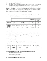
Older models required 9V - 15V.  Models are listed on page 28, and you can check the

model of your unit from the label on the bottom of it.

14

1892 1139 - RSX Range of Intelligent Modems User Guide -  v7.1 / Nov 2007

Alternatively, you can send single serial bytes (for example, from a terminal) to select a
new channel.  See page 18.

Modem parameters are set separately: see page 20.

2.2.1

Programming Adaptor for use with SNx50.exe software

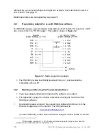
The RSXn50 requires a special adaptor cable between itself and the PC serial port, which
also connects the 5 to 15V DC supply

3

.  This cable is shown in 

Figure 12

.

Figure 12

 - Radio programming adaptor

v

The RSXn50 provides true RS232 readback from pin 1, and so should be
compatible with any PC.

2.2.2

Obtaining and Running the Programming Software

v

If you have already obtained and installed the software, go to step 3

v

The Appendix on page 32 contains a reference covering the functions of the
SXn50.exe software.

.
1.

Download the latest version of the programming software SXn50.exe from the
Wood & Douglas site on the internet.  The URL (address) is:

www.woodanddouglas.co.uk


(In case of difficulty, contact Sales at Wood & Douglas, contact details on the last

Содержание RSX150G

Страница 1: ... Guide v7 1 Nov 2007 1 RSX RANGE OF INTELLIGENT MODEMS USER GUIDE 1892 1139 Figure 1 RSX Series Radio Modem Figure 2 OEM version This manual is intended to provide you with sufficient information to install and operate an RSX radio modem correctly ...

Страница 2: ... use with SNx50 exe software 14 2 2 2 Obtaining and Running the Programming Software 14 2 2 3 Changing unit settings 15 2 3 CHANGING CHANNEL USING SERIAL COMMANDS 18 Part Three Programming the Modem 20 3 1 CHANGING MODEM PARAMETERS WINSETGMSK 20 3 1 1 Adaptor Cable 20 3 1 2 Obtaining and Running the Programming Software 20 3 1 3 Connecting 21 3 1 4 Editing Parameters 21 3 2 WINSETGMSK ADDITIONAL F...

Страница 3: ...gurable if required either by sending serial codes or using proprietary set up software obtained from the Wood Douglas website www woodanddouglas co uk or Sales at Wood Douglas The modem uses the SXn50G range of radios which are high quality very compact synthesized transceivers producing 500mW maximum RF output The SXn50G range is approved to EN 300 220 and ETS 300 086 The UHF SX450G is also appr...

Страница 4: ...ounting details Figure 4 RSX in use A whip antenna may be attached directly to the BNC connector and in this case the unit would typically be mounted vertically The antenna must be in a suitable position for example against a metal panel would not be suitable See Figure 4 Otherwise the connection to the antenna should be made with a short length of high quality coaxial cable This is particularly i...

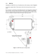
Страница 5: ...ther than the 9 way D type connector shown The unit requires a small amount of heatsinking for the on board regulator to dissipate of the order of 2W This is provided in the cased version by the regulator being screwed down to a supporting pillar in the diecast case The heatsink tab is connected to system 0V and so requires no insulators where the heatsink may be grounded Figure 5 OEM PCB version ...

Страница 6: ...al operation If you are using a computer which has no serial port see the Appendix on page 31 for USB to serial adaptors A power supply of 5 to 15V DC is required1 The current drawn depends on the supply voltage and unit activity as shown on page 10 The remote on off Enable input must be held low 0V when the unit is to operate At other times it can be held high 2V to supply positive to reduce the ...

Страница 7: ... be connected to the serial port of an IBM compatible personal computer using the connections shown in Figure 8 Figure 8 Connections to a PC serial port v These connections are also used when programming the modem not the radio If you are using a computer which has no serial port see the Appendix on page 31 for USB to serial adaptors ...

Страница 8: ...ing OFF 7 4 RTS Ready To Send input RS232 input From external device to RSX See below 8 6 CTS Clear To Send output RS232 output From RSX to external device See below 9 8 PGM Program radio RS232 input Note this input should be left open circuit during normal use n a 7 LED LED Status Output Logic low 0V indicates No Lock error equivalent to orange LED indication Table 1 Connection details 1 2 3 1 RT...

Страница 9: ...ogramming modem with WinSetGMSK Programming radio TX Buffer state Full Not full N A N A Squelch state Don t care Inactive Active N A N A TX Squelch Override Don t care Don t care Disabled Enabled N A N A CTS output Low High Low High Used by software N A 1 2 3 3 PGM This input is used solely for radio programming and has no function during normal use It should be left open circuit as any spurious s...

Страница 10: ...ote Connection to a vehicle supply without proper external transient suppression can cause the internal configuration data to be corrupted Under these circumstances the modem will revert to the default modem settings 1 3 DURING OPERATION 1 3 1 Control Signals The RSXn50 modem uses hardware flow control Whenever customer equipment wishes to send data it should ensure that RTS is high Provided it is...

Страница 11: ... of the enclosure confirms the functional state of the modem RED The modem is in transmit mode GREEN The modem is in receive mode ORANGE The radio has failed i e is out of lock Out of lock may occur if the radio has been programmed incorrectly such that the synthesiser will not lock One cause of this is setting a frequency out of the radio s bandwidth which is set at manufacture The Out of lock st...

Страница 12: ...nable closed enable default setting open disable LK11 Transmitter power 1 2 500mW default setting 2 3 5mW Table 3 Link Settings OEM version only These links are only accessible with the PCB removed from the enclosure and are all on the underside of the board the radio module being on the upper side To remove the PCB from the enclosure 1 Undo the four screws on the top of the unit and remove the li...

Страница 13: ...radio set to use channel 0 However you can select another channel as the current operating channel and or reprogram the table to other frequencies within the switching bandwidth which is a fixed attribute of the radio hardware Certain other parameters are also programmable as detailed below Radio parameters are programmed by connecting a unit to a standard PC serial port using a special adaptor ca...

Страница 14: ...and the PC serial port which also connects the 5 to 15V DC supply3 This cable is shown in Figure 12 Figure 12 Radio programming adaptor v The RSXn50 provides true RS232 readback from pin 1 and so should be compatible with any PC 2 2 2 Obtaining and Running the Programming Software v If you have already obtained and installed the software go to step 3 v The Appendix on page 32 contains a reference ...

Страница 15: ... displayed whenever the software is run The menu bar at the top lists a number of headings under which there are usually additional menu items representing actions Below this there is the Frequency Table The leftmost column lists the channel numbers Ignore the Parallel column The next column TX Frequency is used to set and display channel frequencies Use the Port Setup Com Port COM1 etc menu selec...

Страница 16: ...r a table of 80 individually chosen Tx frequencies and Rx offsets or a table of 256 equally spaced Tx frequencies all with the same Rx offset To select the table type select Parameters Number of Channels 80 or 256 2 2 3 3 Programming 256 Channels as a Block It is necessary to specify the starting frequency the lowest corresponding to channel 0 a spacing or step value and an Rx offset The spacing i...

Страница 17: ...d pick from the list of possible values It is also possible to program a range of channels automatically in a similar way to the 256 channel block In the Frequency Programming Dialog select the range of channels required the From and To drop downs a Table Start and Channel Step and click OK The dialog is removed and the main table shows the channels with their new frequencies It is not possible to...

Страница 18: ...etrieving Configurations It is possible to save and retrieve configurations on disk for later use To save a new configuration select File Save Parameters As To save a previously saved configuration select File Save Parameters To retrieve a configuration overwriting any existing configuration on the screen select File Load Parameters v This feature is also useful if you find that you cannot program...

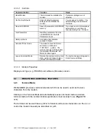
Страница 19: ...ent with an RS232 serial port which can send the required byte Only the TXD to pin 9 and ground to pin 5 connections are required Figure 16 Serial channel change connections terminal pinout shown v If you use a terminal the equivalent keystrokes for channels 0 to 127 are listed in the appendix on page 36 ...

Страница 20: ...aptor Cable The unit should be connected to the computer serial port using the type of cable shown in Figure 8 on page 7 The RTS and CTS connections are essential in this case 3 1 2 Obtaining and Running the Programming Software v If you have already obtained and installed the software go to step 3 1 Download the latest version of the programming software WinSetGMSK exe from the Wood Douglas site ...

Страница 21: ... and parity and clicking Connect If the program tells you that the connection has failed likely reasons are v RSX unit not connected to serial port v RSX unit not powered or supply less than 9V for early units see p 28 v Adaptor not correctly wired see p 7 v Another application on the same computer is using the serial port Figure 17 Connect dialog 3 1 4 Editing Parameters Figure 18 Edit Parameters...

Страница 22: ...3 600 4 1200 5 2400 6 4800 7 38400 Parity RS232 0 no parity 1 odd parity 2 even default The modem works with 8 data bits and parity Modem Mode 0 transmitter only 1 receiver only 2 transceiver default Maximum frame length 0 64 bytes 1 128 bytes default Transmitter start delay 0 to 255 x 5ms Default 2 10ms Transmitter stop delay 0 to 255 Milliseconds Default 1ms Preamble message length 20 225 Length...

Страница 23: ...de The modem enters test mode and sends a continuous 1100110011 pattern The output continues until the button now labelled Deactivate Test Mode is clicked again Leave Command Mode Returns the modem to its normal state waiting to transmit data or go back into command mode The button changes its legend to Enter Command Mode 3 1 4 3 Modem Properties Displays unit type e g RSX450 and software firmware...

Страница 24: ...you type in or the default string of a number and the date and time if you leave the field blank over the air at intervals determined by the Delay field Select the Telemetry Test tab which automatically leaves command mode fill in the details and click Start The button legend changes to Stop click it to end the test Figure 20 Telemetry Test mode ...

Страница 25: ...rs escape that is two bytes of numerical value 27 and 35 These must be the first two characters since the unit went into receive mode This may conveniently be arranged by lowering RTS briefly and raising it again When the unit accepts the command it responds with the characters CR LF Commands may then be given by sending a single byte command code sometimes followed by a second parameter value byt...

Страница 26: ...ings D 68 no second byte Enter all default parameter settings and re initialise the modem The default settings are as listed in this table Full reset R 82 no second byte This command re initialises the modem but does not affect parameter settings Save and exit command mode S 83 no second byte Leave command mode after saving all parameters in EEPROM memory Test Mode T 84 no second byte The modem en...

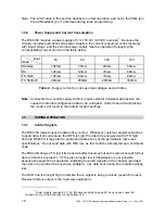
Страница 27: ...or the transmitter and receiver antennas 0dB loss for connectors and cables between the antenna and the radio connector 20dB fade and environmental margin 100dBm received signal strength allowing for the GMSK modulation Range versus TX power Frequency MHz Power mW Power dBm Range km Range miles RSX150G 173 1mW 0 1 7 1 1 173 10mW 10 4 4 2 7 173 100mW 20 13 8 8 6 173 500mW 27 30 9 19 2 RSXn50G 458 5...

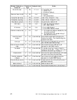
Страница 28: ...tter at the end may be ignored for the purposes of this table Model number range Model Features 9 15V supply 5 15V supply SXn50 radio SXn50G radio Pb free WD1604 board WD2121 board WD2135 board This manual fully applies 01178 1700 01178 2101 RSX450 t t t 01178 2401 01178 2402 RSX150 t t t 01178 2501 RSX850 t t t 01202 1501 RPS960 t t t 01208 1715 01208 2013 RSX450 t t t 01208 2014 RSX450G t t t 01...

Страница 29: ...s Total I P O P Time ms Aggregate Baud Rate RS232 baud rate 9600 9600 42 80 130 3554 9600 332 125 540 6763 9600 2402 125 2950 8957 4800 42 141 191 2419 4800 332 283 890 4103 4800 2402 283 5235 5047 RS232 baud rate 19200 9600 42 80 103 4485 9600 332 150 452 8080 9600 2402 150 2563 10309 NOTES 1 The Input Output delay is measured from the first start bit of the input RS232 data at the transmitter to...

Страница 30: ...tion address 0 255 configurable Number of data bits Fixed at 8 Will accept 7 data bits with 8th bit parity in this case set the modem parity to None Parity None odd even configurable Handshaking RTS CTS DCD squelch Supply voltage 5V 15V DC negative earth Supply current Varies with input voltage see table on p 10 Tx Rx switching time 20ms RF power output 500mW High 5mW Low as standard link selectab...

Страница 31: ...follow the on screen instructions for your version of Windows When the installation is complete proceed as follows to find its COM port number 1 Open the Control Panel Start Settings Control Panel and open the System control 2 Select Hardware Device Manager and expand the Ports COM LPT folder 3 Find the entry labelled USB Serial Port COM n and note the number n 4 Close the Device Manager System an...

Страница 32: ...at 2 allowing 80 channels with IF offsets Format 1 is only used with legacy SX450 modules Save Report File Save the current report A default name is given which you can change and you can navigate to the directory of your choice Print Print the current set of parameters only available when Report File window is open The currently selected Windows default printer will be used Update Firmware Replac...

Страница 33: ...l ports on your machine to communicate with the SXn50G View Main Menu Turns on and off display of the Main Menu window Internal EEPROM This displays the contents of the unit s EEPROM in a separate window The data displayed is for the functions and channels displayed on the main screen at that time Data can be hand modified by highlighting the data and over writing it Note that the type of data in ...

Страница 34: ...transmit frequency Rx Frequency The receive frequency which may be different if an Rx offset has been selected Rx Offset The amount by which the Rx frequency is higher than the Tx frequency Unit Information This box is display only and cannot be edited File Name The name of the firmware running in the unit File Version The version of firmware running in the unit File Date The date of the firmware ...

Страница 35: ...o the transmit band and is used by the software as a base line for all other frequency information The software will not allow a channel to be set to a frequency below this minimum or in the case of a received channel this frequency plus the receive offset This frequency is stored in the non volatile EEPROM in the unit ...

Страница 36: ...69 Shift E 101 E 6 Ctrl F 38 Shift 7 70 Shift F 102 F 7 Ctrl G 39 71 Shift G 103 G 8 Ctrl H 40 Shift 9 72 Shift H 104 H 9 Ctrl I 41 Shift 0 73 Shift I 105 I 10 Ctrl J 42 Shift 8 74 Shift J 106 J 11 Ctrl K 43 Shift 75 Shift K 107 K 12 Ctrl L 44 76 Shift L 108 L 13 Ctrl M 45 77 Shift M 109 M 14 Ctrl N 46 78 Shift N 110 N 15 Ctrl O 47 79 Shift O 111 O 16 Ctrl P 48 0 80 Shift P 112 P 17 Ctrl Q 49 1 81...

Страница 37: ...Wood Douglas Ltd 2007 Baughurst Tadley Hants RG26 5LP Tel 44 0 118 981 1444 Fax 44 0 118 981 1567 email sales woodanddouglas co uk website www woodanddouglas co uk 1892 1139 RSX Range of Intelligent Modems User Guide v7 1 Nov 2007 37 ...

Отзывы: