


8
1892 1139 - RSX Range of Intelligent Modems User Guide - v7.1 / Nov 2007
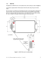
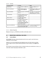
1.2.3
Detailed Information
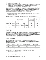
9-way D-type socket
10-way IDC header
Pin
Pin
Name
Function
In/out
Remarks
1*
1*
DCD Data Carrier
Detect/Readback
RS232
output
+10V = signal received, squelch open
-10V = no signal received, squelch closed.
In radio configuration mode, Readback.
2
3
RXD Data output from
modem
RS232
output
Serial data from modem to external device
3
5
TXD Data input to
modem
RS232
input
Serial data from external device to modem
4
10
+V
Supply
Input
5 to 15V DC supply (but see p.28 for
earlier models)
5
9
GND 0V
Ground System Ground
6
2
EN
Enable
Input
Remote ON/OFF
0V = ON, +V (supply) or floating = OFF
7
4
RTS Ready To Send
input
RS232
input
From external device to RSX. See below.
8
6
CTS Clear To Send
output
RS232
output
From RSX to external device. See below.
9
8
PGM Program radio
RS232
input
Note:
this input should be left open circuit
during normal use.
n/a
7
LED
LED Status
Output
Logic low (0V) indicates No Lock error
(equivalent to orange LED indication)
Table 1
- Connection details
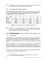
1.2.3.1
RTS
This table summarises what the RSX
n
50 expects to see on the RTS input under various
circumstances:
Modem
function
Normal Operation
Programming
modem with
WinSetGMSK
Programming
radio
Transmitting data
Idle
RTS
state
High
Don’t care
True connection to PC
Ignored
May be wired high or true connection
1.2.3.2
CTS
During normal operation, the RSXn50 takes the CTS output low to inhibit data input from
customer equipment. This is necessary under two circumstances:


