


140721
PRODUCT
MANUAL
PCM-MIO-G-1 24
Register Definitions (WS16C48)
REGISTERS
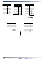
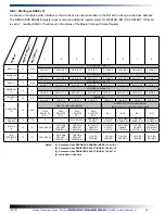
The PCM-MIO uses the WinSystems exclusive ASIC device, the WS16C48. This device provides 48 lines of digital
I/O. There are 17 unique registers within the WS16C48. The following table summarizes the registers, and the text that
follows provides details on each of the internal registers.
BASE+
I/O Address Offset
Page 0
Page 1
Page 2
Page 3
16
00H
Port 0 I/O
Port 0 I/O
Port 0 I/O
Port 0 I/O
17
01H
Port 1 I/O
Port 1 I/O
Port 1 I/O
Port 1 I/O
18
02H
Port 2 I/O
Port 2 I/O
Port 2 I/O
Port 2 I/O
19
03H
Port 3 I/O
Port 3 I/O
Port 3 I/O
Port 3 I/O
20
04H
Port 4 I/O
Port 4 I/O
Port 4 I/O
Port 4 I/O
21
05H
Port 5 I/O
Port 5 I/O
Port 5 I/O
Port 5 I/O
22
06H
Int_Pending
Int_Pending
Int_Pending
Int_Pending
23
07H
Page/Lock
Page/Lock
Page/Lock
Page/Lock
24
08H
IRQ_REG
Pol_0
Enab_0
Int_ID0
25
09H
REV_LO
Pol_1
Enab_1
Int_ID1
26
0AH
REV_HI
Pol_2
Enab_2
Int_ID2
D7
D6
Page
0
0
Page 0
0
1
Page 1
1
0
Page 2
1
1
Page 3
Register Details
Port 0 through 5 I/O
Each I/O bit in each of the six ports can be individually programmed for input or output. Writing a
0
to a bit position
causes the corresponding output pin to go to a high-impedance state (pulled high by external 10 KΩ resistors). This
allows it to be used as an input. When used in the input mode, a read reflects the inverted state of the I/O pin, such that a
high on the pin will read as a
0
in the register. Writing a
1
to a bit position causes that output pin to sink current (up to 12
mA), effectively pulling it low.
INT_PENDING
This read-only register reflects the combined state of the INT_ID0 through INT_ID2 registers. When any of the lower
three bits are set, it indicates that an interrupt is pending on the I/O port corresponding to the bit position(s) that are set.
Reading this register allows an Interrupt Service Routine to quickly determine if any interrupts are pending and which I/O
port has a pending interrupt.
PAGE/LOCK
This register serves two purposes. The upper two bits select the register page in use as shown here:
Bits 5-0 allow for locking the I/O ports. A
1
written to the I/O port position will prohibit further writes to the corresponding
I/O port.
Artisan Technology Group - Quality Instrumentation ... Guaranteed | (888) 88-SOURCE | www.artisantg.com