


140721
PRODUCT
MANUAL
PCM-MIO-G-1 15
Command Register
Each A/D device contains an 8-bit command register to configure the inputs to single-ended or differential mode and the
desired input range (0V - 5V, 0V - 10V, ±5V, and ±10V). The following describes the register options.
INPUT RANGE
7
6
5
4
3
2
1
0
SGL / DIFF
ODD SIGN
SELECT 1
SELECT 0
UNI
GAIN
NAP
SLEEP
MUX CHANNEL SELECTION
NOT SUPPORTED
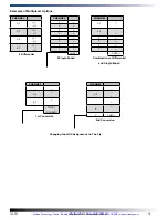
Channel Selection
Bits 7 - 4 of the command register assign the channel configuration for the requested conversion. The converter will
measure the voltage between the two channels indicated by the + and - signs in the table below. In differential mode
measurements are from any of the four adjacent input pairs in either polarity. In single-ended mode, all input channels are
measured with respect to GND. Both the + and - inputs are sampled simultaneously so commode mode noise in rejected.
Range Selection
Bits 3 and 2 of the command register determine the input range for the conversion. Setting UNI to a logical one selects a
unipolar conversion while a zero selects bipolar. The GAIN bit selects the input span for the conversion in conjuntion with
the UNI bit. The table below defined the selection options.
3
2
UNI
GAIN
INPUT RANGE
0
0
±5V
1
0
0V to 5V
0
1
±10V
1
1
0V to 10V
Input Range Selection
MUX ADDRESS
DIFFERENTIAL CHANNEL SELECTION MUX ADDRESS
SINGLE-ENDED CHANNEL SELECTION
SGL/
DIFF
ODD
SIGN
SELECT
0
1
2
3
4
5
6
7
SGL/
DIFF
ODD
SIGN
SELECT
0
1
2
3
4
5
6
7
COM
1
0
1
0
0
0
0
0
+
-
1
0
0
0
+
-
0
0
0
1
+
-
1
0
0
1
+
-
0
0
1
0
+
-
1
0
1
0
+
-
0
0
1
1
+
-
1
0
1
0
+
-
0
1
0
0
-
+
1
1
0
0
+
-
0
1
0
1
-
+
1
1
0
1
+
-
0
1
1
0
-
+
1
1
1
0
+
-
0
1
1
1
-
+
1
1
1
1
+
-
Multiplexer Channel Selection
Artisan Technology Group - Quality Instrumentation ... Guaranteed | (888) 88-SOURCE | www.artisantg.com