


WiNRADiO G315 VHF/UHF Receiver
88
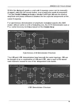
Appendix E – Inside WR-G315 Demodulator
The internal structure of the G315 demodulator is easily accessible by
pressing the
Study
button in the demodulator panel.
The G315 Demodulator relies on a general quadrature representation of the
incoming modulated signals. Such signals can always be considered as the
sum of two amplitude-modulated carriers having a 90 degree offset, usually
referred to as
I & Q
.
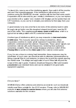
AM Demodulator Structure
The demodulator structure windows include two spectrum analyzers making it
possible to view signal spectra in real-time. Each analyzer can be associated
with any of the
test points
shown as green dots in the diagram. To connect
the left spectrum analyzer to a particular test point, left-click on the green test
point. Its color will change to red. Right-clicking on a dot will connect it to the
right analyzer, and the color will change to blue. If both displays are connected
to the same test point, the point color will turn magenta.
Содержание G315
Страница 1: ...WiNRADiO G315 VHF UHF Receiver User s Guide...
Страница 100: ...WiNRADiO G315 VHF UHF Receiver 100...