WORKSHOP MANUAL
Winget Mechanically Fed Mixers
Models: 200TM
From 1998
Trunnion Removal/Replacement
Remove the drum, engine housing lid, top plate, chain guards and infill plate in the
engine housing. Remove the upper and lower tilting chain guards and remove the
tilting chain. Remove the engine drive chain, undo and remove the two setscrews
retaining the journal and the two nuts securing the front bearing, attach lifting suitable
equipment to the trunnion and take the weight, remove the front bearing.
Note, to remove the trunnion fully it will be necessary to rotate the trunnion as it is
being lifted in order for it to clear the engine housing.
Slide the trunnion towards the engine housing until it can be seen that the travel stop
pegs welded in the front leg and trunnion end plate are clear of each other, rotate the
trunnion and move backwards and upwards to clear the engine housing.
Place the trunnion on a suitable surface and remove the bevel pinion housing and
journal as previously described.
When replacing a 200TM trunnion ensure it has three travel stop pins, part no
513310000 welded into the front plate.
Reverse the procedure to rebuild the trunnion and refit it into the mixer referring to
the relevant sections to set up bevel pinion, journal, front bearing, drum etc.
Hydraulic Hopper Ram
The single acting hopper ram is retained via two pivot pins, to remove fully raise the
hopper and engage the hopper support. Disconnect the hydraulic hoses, note later
rams have a return hose vented back to the hydraulic tank whilst earlier rams have a
small breather hole open to atmosphere. Support the weight of the ram and remove
both pivot pins lift the ram clear of the mainframe.
If installing a seal kit note that later rams vented back to tank have additional wiper
and pressure seals fitted in the cylinder end cap. Also some machines do not have a
loose travel restrictor in the form of a small spacer installed on the piston rod.
Reverse the procedure to refit the ram coating the pivot pins with anti-seize
compound and not forgetting to install the grease nipples, straight into the cylinder
base, 90 degree angled into the piston rod.
Refit the hoses, start the engine or motor and slowly extend the piston via the control
valve, the movement may be ‘jerky’ as the system will be contaminated with air, refit
the upper pivot pin and continue to extend the rod to raise the hopper, disengage the
hopper support and lower the hopper. Stop the engine motor and top up the hydraulic
oil tank. Start the engine/motor and lower and raise the hopper a number of times to
fully expel all the air from the system.
Содержание 200TM
Страница 3: ...WORKSHOP MANUAL 200TM SECTION 1 INTRODUCTION...
Страница 6: ...WORKSHOP MANUAL 200TM SECTION 2 REPAIR SERVICE PROCEDURES...
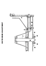
Страница 12: ...200TM DRUM ADJUSTMENT...
Страница 42: ...WORKSHOP MANUAL 200TM SECTION 3 GENERAL ARRANGEMENT DIMENSIONS...
Страница 43: ...GENERAL ARRANGEMENT...
Страница 44: ...DIMENSIONS...
Страница 45: ...WORKSHOP MANUAL 200TM SECTION 4 SERVICE SCHEDULES LUBRICATION DIAGRAM...
Страница 48: ...LUBRICATION POINTS...
Страница 49: ...LUBRICANTS...
Страница 50: ...WORKSHOP MANUAL 200TM SECTION 5 HYDRAULIC CIRCUIT DIAGRAMS...
Страница 51: ...200TM LATER BASIC HYDRAULIC CIRCUIT...
Страница 52: ...200TM LATER DRAGLINE BATCHWEIGER HYDRAULIC CIRCUIT...
Страница 53: ...WORKSHOP MANUAL 200TM SECTION 6 WIRING DIAGRAMS...
Страница 59: ...Hourmeter lamp dwg 04 03 02 12 50 36 Scaled to fit...
Страница 60: ...Hourmeter no lamp dwg 04 03 02 12 53 33 Scaled to fit...
Страница 62: ...WORKSHOP MANUAL 200TM SECTION 7 NOISE LEVELS...
Страница 64: ...WORKSHOP MANUAL 200TM SECTION 8 SPECIAL TOOLS...
Страница 65: ...200TM PUNCH VALVE SEAT 200TM SPECIAL TOOL V2003698 CASE HARDEN TO 45 50 ROCKWELL...
Страница 66: ...200TM DRUM BLADE DRILLING GUIDE SPECIAL TOOL 200TM 513360100...
Страница 67: ...200TM SPECIAL TOOLS...
Страница 68: ...1 513204000 CLAMP DRUM CLIP 1 2 V2003698 PUNCH BLEED VALVE SEAT 1 200TM SPECIAL TOOLS...
Страница 69: ...WORKSHOP MANUAL 200TM SECTION 9 HYDRAULIC CONTROL VALVE SERVICE MANUAL...
Страница 70: ...PAGE INTENTIONALLY BLANK...
Страница 71: ...WORKSHOP MANUAL 200TM SECTION 10 PARTS LISTINGS...
Страница 73: ...200TM MAINFRAME AXLES AND STABILISERS...
Страница 90: ...200TM 415 VOLT START STOP SWITCH STAR DELTA...
Страница 92: ...200TM 415 VOLT START STOP SWITCH DIRECT ON LINE...
Страница 94: ...200TM HOPPER CRADLE BASIC NON WEIGHER COAT ALL PINS AND BEARINGS WITH COPPERSLIP BEFORE INSTALLATION...
Страница 98: ...200TM HOPPER...
Страница 99: ...1 513310900 HOPPER ASSEMBLY 1 2 172S05D BOLT COACH 8 3 267S07 WASHER FLAT 8 4 61S05 NUT BINX 8 200TM HOPPER...
Страница 110: ...200TM WATER TANK FIT SPECIAL WASHER V2004220 BETWEEN ITEMS 11 12...
Страница 114: ...200TM DYNAMO AND MOUNTING LISTER PETTER TS1 HS...
Страница 118: ...200TM DRAGLINE ASSEMBLY...
Страница 120: ...200TM DRAGLINE ASSEMBLY...
Страница 124: ...200TM DRAGLINE SHOVEL...
Страница 126: ...200TM DRAGLINE FEEDAPRON...
Страница 128: ...200TM BATTERY TRAY LISTER PETTER TS1 ES WELD TRAY TO THE REAR OF THE MAINFRAME BELOW THE ENGINE HOUSING...
Страница 130: ...200TM LISTER PETTER TS1 ELECTRIC START...
Страница 132: ...200TM DECALS AND LOGOS 1 2 3 4 5 6 7 8 9 10 11 12 13 14 15 16 17 18 19 20 21 22...
Страница 134: ...200TM DECALS AND LOGOS 23 24 25 26 27 28 29...
Страница 135: ...200TM SPECIAL TOOLS...
Страница 136: ...1 513204000 CLAMP DRUM CLIP 1 2 V2003698 PUNCH BLEED VALVE SEAT 1 200TM SPECIAL TOOLS...
Страница 137: ...WORKSHOP MANUAL 200TM SECTION 11 BATCHWEIGHER MAINTENANCE INSTRUCTIONS...
Страница 138: ...MAINTENANCE INSTRUCTIONS HYDRAULIC WEIGHING UNITS WWW WINGET CO UK...
Страница 140: ......
Страница 141: ......
Страница 142: ......
Страница 143: ......
Страница 144: ......
Страница 145: ......
Страница 146: ......
Страница 147: ......
Страница 148: ...WORKSHOP MANUAL 200TM SECTION 12 18 BLANK...

