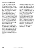


MAINTENANCE
CUTTER 24V 86036830 06/20/07
4-6
2. SQUEEGEE BLADES
The front squeegee blade allows solution to pass
through channels in the blade into the squeegee
assembly while maintaining vacuum to provide lift.
The front blade has four wear surfaces and can be
rotated for extended life. The front blade should not
require regular replacement under normal use.
The rear blade wipes the floor to a near dry
condition. It is important the rear blade be in good
condition to properly do its job. As with the front,
each squeegee blade assembly has four wear
surfaces for extended service.
Check both the front and rear squeegee blades for
damage, wear, and adjustment each day in the pre-
run check. Change the front blade if it is torn or has
an uneven edge. Change the rear blade if it is less
than 1/2 the original thickness.
ADJUSTING SQUEEGEE
Adjusting the squeegee is a two-part process. First,
the squeegee assembly must have correct pitch in
order for the squeegee blade to have the same
deflection at each tip as well as the center. The
knob on the squeegee linkage controls the pitch
adjustment. The second adjustment is the
deflection. Knobs on each end of the squeegee
control this.
TO REMOVE SQUEEGEE ASSEMBLY
1.
With the squeegee in the up position, turn key
switch “OFF”.
2.
Disconnect vacuum hose from squeegee and
loosen both knobs.
3.
Pull squeegee assembly rearward from the
lifting carrier.
4.
Inspect or repair as necessary and reinstall.
TO REPLACE OR ROTATE REAR
SQUEEGEE BLADES
1.
With the squeegee in the up position, turn key
switch “OFF”.
FOR SAFETY: Before leaving or servicing
machine; stop on level surface, turn off machine
and remove key.
2.
Remove the squeegee assembly from the
machine. Unlatch and remove blade retainer
strap and remove squeegee blade.
3.
Rotate the squeegee to new edge position or
replace as required. Each blade has four new
edge positions.
4.
Install blade on locating pins of squeegee
assembly.
5.
Install squeegee retainer strap.
6.
Fasten and lock latch, adjust latch only tight
enough to take up slack in retaining strap.
TO REPLACE OR ROTATE FRONT
SQUEEGEE BLADE
1.
With the squeegee in the up position, turn key
switch “OFF”.
2.
Remove the squeegee from the machine.
Loosen three thumbscrews and remove the
retainer strap and squeegee blade.
3.
Rotate the squeegee to new edge position or
replace as required. Each blade has four new
edge positions. When installing the front blade,
tighten the center thumbscrew first. Insure that
the retainer strap is pressed against the blade
before tightening the outer screws.
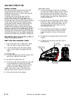
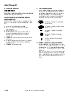
SQUEEGEE SIDE VIEW OF
CORRECT
NOT ENOUGH
TOO MUCH
SQUEEGEE DEFLECTION
Содержание Saber Cutter 10052360
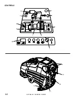
Страница 12: ...CONTROLS CUTTER 24V 86036830 06 20 07 3 5 3 5 8 6 13 9 2 12 11 15 1 14 7 10 4 16 ...
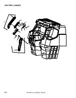
Страница 34: ...CONTROL HANDLE CUTTER 24V 86036830 06 20 07 11 9 6 10 8 7 4 5 2 3 1 5 1 ...
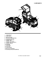
Страница 36: ...COVER FRONT TANK MOUNT CUTTER 24V 86036830 06 20 07 10 9 8 7 5 1 2 6 2 3 3 5 3 ...
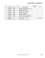
Страница 38: ...COVER TOP TANK MOUNT CUTTER 24V 86036830 06 20 07 8 5 7 1 2 3 4 3 5 3 6 3 9 10 11 5 5 ...
Страница 40: ...DECAL CUTTER 24V 86036830 06 20 07 1 2 3 5 6 7 4 5 7 ...
Страница 44: ...LIFT HANDLE CUTTER 24V 86036830 06 20 07 8 6 1 7 2 1 9 4 5 3 5 11 ...
Страница 46: ...LIFT HANDLE LINKAGE CUTTER 24V 86036830 06 20 07 4 9 16 1 5 3 2 7 6 10 11 8 12 13 6 14 15 17 5 13 ...
Страница 50: ...SCRUB BRUSH PAD DRIVER 3 5 1 8 9 4 6 5 7 2D 2E 2A 2C 2B CUTTER 24V 86036830 06 20 07 5 17 ...
Страница 54: ...SCRUB DECK MOTORS CUTTER 24V 86036830 06 20 07 5 21 8 6 7 9 10 4 5 3 2 1 ...
Страница 60: ...SCRUB DECK LIFT CUTTER 24V 86036830 06 20 07 3 2 1 6 7 8 12 5 2 1 10 2 13 13 7 9 7 11 5 4 7 5 27 ...
Страница 62: ...SCRUB DECK LIFT CUTTER 24V 86036830 06 20 07 15 16 13 12 9 10 11 6 5 8 7 5 4 3 2 6 1 17 18 14 15 15 12 5 29 ...
Страница 64: ...SOLUTION CUTTER 24V 86036830 06 20 07 14 3 2 1 4 6 7 8 9 13 10 12 11 HOSE FROM FILTER ASM 5 5 31 ...
Страница 66: ...SOLUTION CUTTER 24V 86036830 06 20 07 7 2 3 8 4 10 9 1 5 13 12 11 10 4 6 5 33 ...
Страница 70: ...SQUEEGEE LIFT LINKAGE LOWER CUTTER 24V 86036830 06 20 07 1 2 3 4 5 6 7 1 8 9 10 14 15 16 17 13 11 12 5 37 ...
Страница 72: ...VACUUM CUTTER 24V 86036830 06 20 07 4 3 2 7 8 9 6 5 1 2 1 5 39 ...
Страница 74: ...WHEELS AND FRAME CUTTER 24V 86036830 06 29 11 5 41 4E 4D 6 8 7 9 10 1 2 5 4A 4C 3 4B 11 ...
Страница 76: ...WIRING BATTERY CUTTER 24V 86036830 02 10 09 5 43 1 2 3 4 5 9 6 7 8 1 11 10 12 13 ...
Страница 83: ...CUTTER 24V 86036830 06 20 07 5 50 THIS PAGE LEFT BLANK INTENTIONALLY ...
Страница 86: ...EMERGENCY STOP OPTION CUTTER 24V 86036830 06 20 07 1 5 53 ...
Страница 91: ...NOTES CUTTER 24V 86036830 06 20 07 5 58 ...
Страница 92: ...CUTTER 24V 86036830 06 20 07 5 59 ...