background image

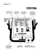
COMMODORE 1 

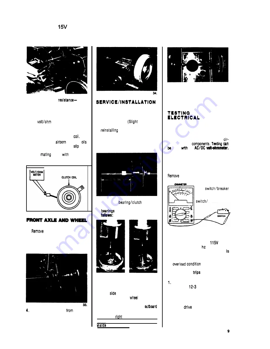
32. 

To check clutch coil 

1. 

Disconnect machine power cord from 

2. 

Disconnect clutch lead connection. 

3. 

Set 

meter to check ohms. 

4. 

Connect  meter  leads  to  clutch leads. 
If the meter reads below 

160 

ohms 

or above 195 ohms replace 
Accumulation of 

dust and 

may  bause  the  clutch  to 

and 

lose  traction.  Remove  clutch  and 

clean 

parts 

a  cleaning 

solvent. 

outlet. 

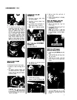
ASSEMBLY REMOVAL 

1. 

drive chain (see Photo 

28). 

2. 

Lay machine on side. 

3. 

Remove  nuts  and  bolts  holding 

flange bearing to frame. 

Remove axle assembly 

machine 

and put on workbench to service. 

5. 

Remove  snap  ring  on  each  end  of 

axle 

to 

remove wheels. 

WHEEL AND AXLE 

1. 

Install  flange  bearing  on  axle. 

Po- 

sition set screws (in locking collars) 
over  innermost  flats  on  axle  and 
tighten  screws. 

adjustment 

of  bearings may be necessary when 

assembly to frame.) 

2. 

When  replacing  sprocket  on  axle 
note  dimension 

approximately 

5/16 

from  end of  axle  to  face  of 

sprocket.  (Photo 

33) 

35. 

3. 

Replacing 

bearings 

in  wheels.  Thsss  are  directional 

and  must  be  Installed as 

36. 

LEFT WHEEL: 

Bearing must be 

pressed in from 

inboard 

of 

wheel with knurbd 
end of  bearing 
sleeve on Inboard 
side of  wheel. 

37. 

RIGHT 

WHEEL: 

Bearing must be 
pressed in from 

outboard side of 

with knurled 

end of  bearing 
sleeve on 
side of  wheel. 

NOTE: 

Both 

and left bearing 

assem- 

blies must be pressed 

in 

flush with the 

of  wheel hubs. 

38. 

4. 

To  check  assembly:  hold  axle 

each  wheel  should  rotate  forward 
freely  and  lock  on  shaft  when  rota- 
tion is reversed. 

COMMODORE 

CIRCUITS: 

CAUTION:  Repalrs  should  only  be  at- 

tempted  by  qualified  personnel  since 
damage  can  be  done  by  persons  not 
experienced 

in 

working with  printed 

cuit 

boards and 

done 

an 

SWITCHES AND 

CIRCUIT 

BREAKERS 

them  from  machine and  use an 

ohmmeter or continuity tester. The correct 

reading  is zero for an 

open 
and  infinity  (conti- 
nuity)  for  a  closed 

brea ker 

BRUSH DRIVE MOTOR 

This  motor  operates  on  a 

60  hz 

circuit 

(or 

230V 

50 

depending  on 

machine  model).  A 

amp  breaker 

Installed 

in  the  drive  motor  circuit 

to 

prevent  damage  to  the  motor  in case 
an 

occurs. 

If the  breaker 

after  being 

reset, 

check for probable cause: 

Incorrect  power  cord.  Use  nothing 

less  than 

cable wire  size  and 

no longer than 

100 

ft 

2. 

Brush height  lever set  too  low.  Ad- 

just to correct height. 

3. 

Faulty 

motor.  Repair  or  re- 

place as  required. 

4. 

Brush assembly  “locked-up.”  Check 

for obstruction 

faulty  brush bear- 

ings,  etc. 

Содержание COMMODORE CMD

Страница 1: ...COMMODORE 115V 98048 Model CMD I WINDSOR INDUSTRIES INC 1351W Stanford Ave Englewood CO 80110USA 303 762 1800 FAX 303 7626817 ...

Страница 2: ... not pick up burning materials such as cigarettes or matches 3 Do not leave the machine unattended Unplug machine from power outlet when not in use 4 Switch off switches before disconnecting power cord from electrical outlet 5 Maintenanceand repairs must be done by qualified personnel 6 Do not disconnect cord from outlet by pulling on cord Grasp plug to remove from outlet 7 Do not use power cord a...

Страница 3: ...otor Glows red pelllng speed from position to lower vac when on stop to 4 max shoe assembly to carpet as well as start vacuum motor CIRCUIT BREAKER Protects brush drive motor from burn out Pushto reset after correcting problem CLUTCH LEVER Pushdown to propel when DRIVE MOTOR is on DRIVE MOTOR LINE FUSE Protectsdrive motor and circuit board Replace fuse after correcting problem 3 ...

Страница 4: ...r and grounding plug The plug must be plugged Into an appropriate outlet that is properly Installed and grounded In accordance with all local codes and ordinances WARNING Improper con nection of the equipment groundingcon ductor can result in a risk of electrical shock Check with a qualified electrician or service person if you are in doubt as to whether the outlet is properly grounded Do not modi...

Страница 5: ...to 4 depending upon the condition of the carpet being cleaned Forward speeds and approximate coverages are I COVERIOE SQtJARE I I IFEET PER HOUR Straight ahead SPEED cleaning no SETTINO FPM allowances I I I SPRAY JETS To prevent clogged jets due to alkaline build up the spray system should be flushed with 2 or 3 gallons of clean hot water at the end of each day The COMMODORE is equipped with quick...

Страница 6: ...ours It is wired into the vac motor circuit so that all operations using the vacuum are recorded REMOVE VACUUM MOTOR to inspect carbon brushes for wear If worn to 3 8 inch the brushes should be replaced See service section for instructions USE COMPRESSED AIR to blow out dust In brush drive motor SERVICING THE COMMODORE WARNING Remove machine power cord from electrical source before mak ing any adj...

Страница 7: ...terminal block 2 Disconnect solution hoses from solenoid valve 3 Lay machine on side and remove 2 screws holding valve to chassis 4 Clean repair or replace as required BELT BRUSH ASSEMBLY REMOVAL 1 Removebelt guard 2 0 2 Lay machine on side and remove brush pulley guard Z1 3 Roll belt off motor pulley 4 Retwve 2 screws holding seal plate 5 Remove screw from each end of 6 Swing brush assembly out o...

Страница 8: ...justing rods after completing vac shoe adjustment Vac Shoe Hdght Adjustment Placemachineon smooth shoe Lever should have level surface lower vac approximately 1 of additional forward travel when properly adjusted Lengthen or shorten lift rods A B as required Fig 4 TO ADJUST VAC SHOE TRACKINO 1 With machine moving forward check vac shoe for tracking 2 If shoe pulls to the LEFT tighten right hand sp...

Страница 9: ... end of bearing sleeve on Inboard side of wheel 37 RIGHT WHEEL Bearing must be pressed in from outboard side of wheel with knurled end of bearing sleeve on outboard side of wheel NOTE Both right and left bearingassem blies must be pressed in flush with the hride of wheel hubs 38 4 To check assembly hold axle each wheel should rotate forward freely and lock on shaft when rota tion is reversed TESTI...

Страница 10: ...30 volt models Use DC volt meter to check DC output voltage at terminals A and A With the speed control knob set at MAX 4 DC volts should be 95 VDC f 10 if there is 0 voltage or the voltage does not remain constant this is an indication that the circuit board is faulty Replaceas required TO TEST TRAVIRSI DRlVB MOTOR To test for around or short circuit first disconnect machine power cord from elect...

Страница 11: ...COMMODORE 115V CONTROL PANEL ASSEMBLY I COMMOOOAE CONTROL PANEL ...

Страница 12: ...2 CHASSISWIDRIVE ASSEMBLY ...

Страница 13: ...hwl CMDmachlnd 1 09011 0Wla A m whad 8 87038 Hhshsr 5 8wIM 9 27122 Cc kr ShaN 10 70126 W Scr 1 4 28 x 114KCP 11 o mos 06XhQ W8 Ancr 12 03012 Ark whd 13 73045 SpratkU 1 3 5W8 P 25 beth 14 4llOll8 Kap 3 16x1 75 15 4o ls w 18Wdrufl 17 57032 Nut 3 8FlanprLock 18 70043 Scr 10 32x 3 4 FHUS 16 22012 CWU 3 8ODSt Thru 4 8 0 0 E I 0 0 0 A m ...

Страница 14: ...COMMODORE 1 15V 14 ...

Страница 15: ...cr 1032x 1 2fWMS 15 27281 Cap Brush HouslnqEnd 17 36070 Guard Splash 18 67106 Relalner SplashGuard 19 70066 W 10 32x 314 PHMS 20 36051 Guard Thread 21 09019 BsarhrpI Brush 22 67098 Wnp T o k m o 23 12006 Bush 24 70177 Scr 1632x 112FHMS 25 62171 pl dS Pulby seal 11 57047 Nut 1 4 20 lock 16 57090 Nu 10 321o k 26 73241 h i Pulley 27 35085 Gasket Seal PMe I 76 11019 Bell CMO Brush Drive I 8 E R K K 0 ...

Страница 16: ...COMMODORE 115V SQtUTION RECOVERY TANKS 16 ...

Страница 17: ...COMMODORE 115V CONTROL PANEL WIRING DIAGRAM 115 VOLT m n avoc 1 rl wllc I I I I w T 1 CHASSIS WIRING DIAQRAM 11S VOLT n I 17 ...

Страница 18: ...COMMODORE 115V CONTROL PANE1 WIRING DIAGRAM 230VOLT CHASSIS WIRING DIAORAM 230 VOLT A I8 i 18 ...

Страница 19: ...brushesin gear drive motor or faulty motor Fuse blown or circuit breaker tripped on machine Faulty speed control potentiometer Faulty pump Faulty switch Clogged or faulty solenoid Obstruction in jets Faulty switch Dirt in solenoid valve or faulty valve One or more jets plugged SOLUTlON Check buildingcircuit breakero r fuse box Replace switch Repair or replacepower cord Replacefuse or reset breaker...

Отзывы: