COMMODORE 1
1.
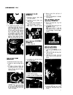
Remove belt guard.
2.
Roll belt off motor pulley.
3.
Loosen set screws in locking collars
on pivot shaft. Slide out shaft to
lower brush head assembly.
BRUSH DRIVE MOTOR
1.
To
access motor mounting bolts,
lower brush head assembly.
2.
Disconnect motor leads from terminal
block.
3.
(4)
motor mounting screws.
4.
Lift out motor and repair or replace
as required.
NOTE: When reinstalling motor,
make sure pulleys are properly
aligned and belt tension is adjusted
to
prevent slipping.
VACUUM SHOE
1.
Remove upper link arms.
2.
Remove ball joint linkage.
3.
Disconnect
lift
cable from
shoe.
4.
Remove tension springs.
5.
Repair or replace as required.
VAC SHOE ADJUSTMENT
NOTE:
When replacing
shoe or bail
adjust
shoe as follows:
With machine on smooth level
the front and rear shoe of
casting
should be parallel with surface.
1.
If
of shoe is off floor (Fig.
3),
lengthen lower adjusting rods.
2.
If
of shoe is off floor (Fig. 2),
shorten lower adjusting rods.
3.
Retighten lock nuts on adjusting
rods after completing
shoe
adjustment.
Shoe
Adjustment
-
machine on smooth
shoe, Lever should have
level surface, lower
approximately
1"
of
additional forward travel
when properly adjusted.
Lengthen or shorten lift
rods A
as required
(Fig.
4).
TO
ADJUST VAC SHOE
1.
machine moving forward check
shoe for "tracking."
2.
If shoe pulls
to the
tighten right
hand spring adjusting knob.
3.
It
shoe pulls to the
RIGHT tighten
left hand spring adjusting knob.
27.
AND CLUTCH
1.
Disconnect motor leads.
2.
Disconnect leads from clutch
3.
Remove chain. NOTE: Chain has
master link for easy removal.
4.
Remove
(4)
bolts
holding motor
to
chassis and lift out motor.
5.
brush
cap
and inspect motor
brushes periodically. Brushes should
be replaced when they reach
length or after approximately 750
hours. The gear box is
sealed and permanently lubricated
for the
of motor.
CLUTCH REMOVAL
AND
Depending on the duty cycle of the
clutch, periodic inspections and clean-
ing of the clutch parts should
be
made.
1.
Remove
bolt from center of gear unit
shaft.
2.
Remove bolt holding
ing arm.
3.
Remove sprocket from shaft. Use
bearing puller as needed.
Содержание COMMODORE CMD
Страница 11: ...COMMODORE 115V CONTROL PANEL ASSEMBLY I COMMOOOAE CONTROL PANEL ...
Страница 12: ...2 CHASSISWIDRIVE ASSEMBLY ...
Страница 14: ...COMMODORE 1 15V 14 ...
Страница 16: ...COMMODORE 115V SQtUTION RECOVERY TANKS 16 ...
Страница 18: ...COMMODORE 115V CONTROL PANE1 WIRING DIAGRAM 230VOLT CHASSIS WIRING DIAORAM 230 VOLT A I8 i 18 ...


