background image

30

2. 

For the Installer

2.3.24  Mounting the front boiler cover

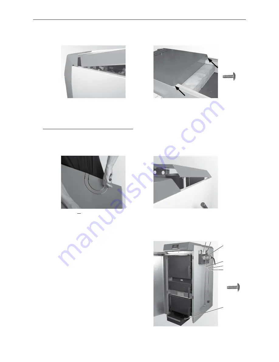
–  Hook the front boiler cover into the side panels (Fig. 63) and attach at rear with 2 self-tapping screws – Fig. 64.

Fig. 63  Hinging in boiler cover

Fig. 64  Securing boiler cover in 2 places

2 x

2.3.25  Mounting the rear boiler cover

–  If no adapter for the flue gas blower (accessories) is being used, break off the cut-out at the rear of the boiler 

cover – Fig. 65.  

large cut-out =  exhaust pipe insulated


small cut-out = exhaust pipe not insulated


do not break off = adapter for flue connection installed

–  Hook the rear boiler cover into the slot provided on the side panel cladding – Fig. 66.

Fig. 65  If no adapter for the flue connection is being 

used, break off the cut-out

Fig. 66  Hooking in the rear boiler cover

Supplied as standard:

1 ........... Instructions
4 ........... Scratcher
7 ........... Ash pan

Optional accessory: cleaning kit EWK 020:

3 ........... Hanger (for installation on the wall or boiler side panel)
2 ........... Spatula
5 ........... Cleaning brush
6 ........... Poker

2.3.26  Instructions, cleaning and operating implements

–  Install the hanger with the instructions folder, cleaning 

and operating implements on a side panel of the boiler 
(Fig. 67) or on a wall in the boiler room/installation room.

–  Keep ash pan under boiler.

4 x

Fig. 67  Fitting hanger, ash pan under 

boiler

3

4
5
6

7

1   2

Содержание LogWIN Klassik

Страница 1: ...WOOD Assembly instructions LogWINKlassik m wood gasification boiler For small and large houses Nominal thermal output 18 25 30 kW 10 2013 093391 01...

Страница 2: ...f performance to that obtained following the guidance given in Approved Document J Please note that it is a legal requirement under England and Wales Building Regulations that the installation of the...

Страница 3: ...esign will provide sufficient draught The outlet from the chimney should be above the roof of the building in accordance with the provisions of Building Regulations Approved Document J Because the boi...

Страница 4: ...boiler is indicated in the brochure The boiler should preferably be installed on a non combustible hearth of a size and construction that is in accordance with the provisions of the current Building...

Страница 5: ...of any electrical services during the installation of this boiler and the associated heating system must be carried out by a registered competent electrician and in accordance with the requirements of...

Страница 6: ...Installing the flue connection adapter 12 2 4 6 Installing the flue gas blower air control and lambda sensor 14 2 4 7 Installing the lighting door with automatic ignition 14 2 4 8 Installing the carbu...

Страница 7: ...safeguard 33 4 4 Technical data for calculating the flue gas system acc to EN 13384 1 for LWK 180 300 34 4 5 Technical data General for LWK 180 300 34 4 6 Dimensional sketches 35 4 7 Service level 36...

Страница 8: ...following classification Temperature class T400 nominal operating temperature 400 C Soot fire resistance class G flue gas system with soot fire resistance Corrosion resistance class 2 suitable for unp...

Страница 9: ...and cleaning of the boiler with reference to the Operating Manual The following preconditions must be met before you order the initial start up 1 Boiler installed correctly 2 System fully wired up ele...

Страница 10: ...ssik 2 1 2 Optional accessories Fitted in control panel if ordered MESplus system control installed and pre wired Supplied with the boiler if ordered Adapter for steplessly adjustable flue connection...

Страница 11: ...uired for systems providing up to 300 kW nominal thermal output if it can be ensured that a lack of water in the system will not result in excess heating If the boiler is above the radiators then a lo...

Страница 12: ...rature stratification in the heat accumulator or buffer tank we recommend that the boiler circuit be regulated When using the return hold up group SK RH 61 in connection with the stratified charge fun...

Страница 13: ...n taking the cover grille discs etc into consideration Information Malfunctions or complaints occasioned by inadequate combustion air will not be covered by the guarantee 1 The boiler s nominal total...

Страница 14: ...er 8 Rear boiler cover 9 Hook in plate ash pan 10 Bottom insulation left right 11 Top insulation left right 12 Top rear insulation 13 Bottom rear insulation 14 Top front insulation 15 Cladding door 16...

Страница 15: ...for transport dimensions Note There is a crane lug on the top of the boiler for transport using hoisting winches The weight can be reduced by approx 120 kg by removing parts which are easy to disassem...

Страница 16: ...nd the dog point screw for attaching the cladding door must be mounted either on the left or right depending on which side the door catches are to be located Fig 7 Fig 7 Install door hinge for claddin...

Страница 17: ...led Secure adapter with slot position depending on desired angle of flue connection on boiler according to Fig 11 with seal and 4 M8 nuts Fig 11 12 0 45 45 90 90 135 135 180 0 45 45 90 90 135 135 180...

Страница 18: ...ten approx 1 4 turn with an open ended wrench SW 22 Fig 14 15 Fig 13 Hooking in air control at top and screwing on at bottom Fig 14 Lambda sensor installed 2 4 7 Installing the lighting door with auto...

Страница 19: ...18 19 Attach the carburisation gas duct and screw tight with 2 M8 nuts Fig 20 Fig 18 Installing 2 fasteners for carburi sation gas duct Fig 19 2 fasteners installed Fig 20 Installing the carburisation...

Страница 20: ...with one self tapping screw and one saw tooth ring for earthing Fig 26 Fig 23 Screw in 2 screws on each side of the base Fig 24 Hooking the side panels in with screws at the bottom 2 each of Note Only...

Страница 21: ...27 Attach the cable channels at left and right feed through at rear with a drilling screw on each side to the front of the control panel leave some overhang over the cladding at the rear approx 5 mm...

Страница 22: ...control sensor at the top Fig 29 Threading through thermocontrol sensor Fig 30 Securing the thermocontrol sensor with spring pulling cable back Fig 31 Thermocontrol sensor with spring 2 4 13 Installin...

Страница 23: ...sor STB as far as possible into the immersion sleeve and secure them with the sensor guard to prevent them from slipping out Fig 34 Install the flue gas sensor with protective tube accessories into th...

Страница 24: ...ough in the side panel downward and connect to the lambda sensor Fig 36 Fig 35 LogWIN Klassik with rear panels removed rear view Air control cable with Plug X6 X7 Air control cable with Plug X14 Lambd...

Страница 25: ...nstalling the rear panels If no adapter for the flue gas blower accessories is being used break off the cut out at the top of the back panel Fig 37 large cut out exhaust pipe insulated small cut out e...

Страница 26: ...and secure with screws inserted only Fig 42 2 4 17 Installing the blower housing on the adapter Only for LogWIN with flue connection adapter accessories First screw the 4 included M8 x 16 hexagon scre...

Страница 27: ...15 Fig 44 Loosely screw the control panel to the side panels 2 x and control panel 2 x with self tapping screws Fig 45 Connect the InfoWIN cable and route into the side panel Fig 45 Fig 43 Threading t...

Страница 28: ...y always includes door catches on the left The catches on the cladding door and boiler doors must be on the same side Fig 46 Lower cladding door on door hinge Fig 47 Upper cladding door with door hing...

Страница 29: ...cladding door is totally closed Fig 50 If necessary use a screwdriver at the top inside the control panel to reset Fig 51 2 4 21 Adjusting the cladding Adjust side panels cladding door and control pan...

Страница 30: ...Mounting the rear boiler cover If no adapter for the flue gas blower accessories is being used break off the cut out at the rear of the boiler cover Fig 54 large cut out exhaust pipe insulated small c...

Страница 31: ...positive pressure in the exhaust pipe for a short period during the starting phase f Insulate the exhaust pipe with at least 30 mm insulation g A draught limiter is needed if the maximum draught see t...

Страница 32: ...must not be possible to block the connection manually Connection according to EN 303 5 6 7 8 1 2 3 4 5 Fig 57 Thermal safety device connection Minimum connection pressure of the thermal safety device...

Страница 33: ...mains connection must be protected against short circuit with a 13 A delayed action fuse We recommend using fine wire PVC sheathed cables e g H05VV F YMM J with a 3 x 1 5 mm2 nominal crosssection The...

Страница 34: ...r Fig 61 Fig 59 Removing the rear boiler cover Fig 60 Loosen 2 screws Fig 61 Lifting boiler cover and pulling off to the rear Check 4 pin plug on InfoWIN cable route to left side from control panel as...

Страница 35: ...Route cables in the cable ducts available Fig 63 Information Electrical cables should be routed in the cable ducts intended for this purpose and are not allowed to be routed over the cleaning cover T...

Страница 36: ...64 Hooking in the front boiler cover Fig 65 Securing with 2 screws Insert the rear boiler cover into the slot provided on the side panel Fig 66 Connect or plug in the mains power plug at the rear of t...

Страница 37: ...ains power plug Attention De energise the boiler before opening the control panel for service or repair purposes Unplug po wer plug Fig 68 4 3 Checking and servicing the thermal process safeguard Plea...

Страница 38: ...nit LWK 180 LWK 250 LWK 300 Boiler class according to EN 303 5 2012 5 Nominal thermal output range kW 13 18 13 25 13 30 Fuel type to EN 303 5 2012 permissible A C21 A C21 A C21 Fuel water content perm...

Страница 39: ...r directly on boiler 93 129 327 227 1267 154 559 1040 120 97 1492 654 277 1437 KV KR E SB SB TV 1101 1188 All dimensions in mm Rear view Left view Flue gas blower directly on boiler flue connection at...

Страница 40: ...Manual Service level Reserved for trained service personnel only Information level see LogWIN operating instructions MES Module1 see separate instructions for InfoWINplus Master operation InfoWINplus...

Страница 41: ...only for trained service personnel 5s Service level Pressing the Menu button Fig 72 shows the Opera tor level Service level Information level and MES Module1 in the display Fig 73 Use the arrow button...

Страница 42: ...rrent boiler temperature is displayed in C Temp chamb The current temperature in the combustion chamber is displayed in C Fan speed The nominal speed of the blower is displayed in rpm Pos Prim airfl T...

Страница 43: ...ESplus thermal distribution module WVF If only Solid fuel operation is set on the WVF Burnout with embers maintenance is undertaken With all other settings on the WVF a normal burnout is undertaken no...

Страница 44: ...k Time format The time is displayed in the chosen format e g 14 12 or 02 12 PM Factory setting 24 h Selection 24 h or 12 h Date format DD MM YYYY MM DD YYYY Choose Back Date format The date is display...

Страница 45: ...s when Ver sion Fig 93 is displayed and the button shown in Fig 93 is pressed for 5 seconds Version is displayed if the R button is pressed for 5 seconds on a stan dard display Fig 92 if the InfoWINpl...

Страница 46: ...define whether MESplus system control is present Factory setting is set in the factory before delivery as per the order Selection yes with MESplus system control no no MESplus system control SMS Yes N...

Страница 47: ...r boiler 100 C X1 X17 X16 X15 X14 X13 X12 X11 X2 X6 X7 X3 X8 X9 X19 2 1 4 3 2 1 3 2 1 6 5 4 3 2 1 2 1 2 1 Lon Lon GND 12V GND Lon Lon 12V 1 2 3 1 2 3 4 1 2 3 4 5 6 1 2 3 1 2 1 2 3 4 011999 L N PE L L...

Страница 48: ...ONS The guarantee and warranty limitations require that the boiler and related accessories be properly installed and started up by Windhager Customer Service or Customer Service Partner otherwise the...

Страница 49: ...WOOD Assembly instructions LogWINKlassik m wood gasification boiler For small and large houses Nominal thermal output 18 25 30 kW 07 2014 093391 02...

Страница 50: ...ek expert advice The most common cause of fume emission is flueway or chimney blockage For your own safety these must be kept clean at all times IMPORTANT NOTES General Before lighting the boiler chec...

Страница 51: ...ions will reduce the possibility of unnecessary damage and corrosion Extractor fan There must not be an extractor fan fitted in the same room as the boiler as this can cause the boiler to emit smoke a...

Страница 52: ...to burn any other type of fuel General Maintenance It is important that any glass or other decorative surfaces are kept clean using the appropriate cleaning materials and techniques as to not damage t...

Страница 53: ...ng the flue gas blower air control and lambda sensor 15 2 3 7 Installing the lighting door with automatic ignition 15 2 3 8 Installing the carburisation gas duct 16 2 3 9 Mount shaft for the lever for...

Страница 54: ...rmal process safeguard 36 4 4 Technical data for calculating the flue gas system acc to EN 13384 1 for LWK 180 300 37 4 5 Technical data General for LWK 180 300 37 4 6 Dimensional sketches 38 4 7 Serv...

Страница 55: ...following classification Temperature class T400 nominal operating temperature 400 C Soot fire resistance class G flue gas system with soot fire resistance Corrosion resistance class 2 suitable for unp...

Страница 56: ...and cleaning of the boiler with reference to the Operating Manual The following preconditions must be met before you order the initial start up 1 Boiler installed correctly 2 System fully wired up ele...

Страница 57: ...e line losses to the system 2 2 2 Standards The following European standard should be followed EN 12828 this specifies that the following should be fitted a A closed expansion tank b A reliably functi...

Страница 58: ...alculate the minimum buffer tank volume 2 2 4 Heating circuits Several heating circuits In line regulating valves should be installed to permit better regulation of the system In a building without in...

Страница 59: ...SWKI BT 102 01 Applicable for Austria excerpt from NORM H 5195 a According to NORM H 5195 2010 edition the condition of the heating water must be checked every 2 years by a heating technician in order...

Страница 60: ...for combustion air should be designed as follows the flow of air must not be restricted in any way by the weather e g snow leaves the free cross section area remains the same when taking the cover gri...

Страница 61: ...or installation Information All cladding parts must be fitted in full for air guidance and the dissipation of heat on the boiler 21 2 3 4 5 6 7 8 9 10 11 12 13 14 15 28 18 19 20 1 22 23 22 24 25 26 27...

Страница 62: ...ving been taken into the building and installed incorrectly or if the appliance malfunctions as a consequence of this The LogWIN may only be transported upright and without cladding and it is easiest...

Страница 63: ...54 565 85 400 2028 2065 1289 All dimensions in mm LogWIN Klassik All dimensions in mm Minimum room heights 1850 mm Fig 5 LogWIN Klassik exhaust pipe upwards top view 498 883 1102 654 min 550 min 400 m...

Страница 64: ...the dog point screw for attaching the cladding door must be mounted either on the left or right depending on which side the door catches are to be located Fig 8 Fig 8 Install door hinge for cladding...

Страница 65: ...led Secure adapter with slot position depending on desired angle of flue connection on boiler according to Fig 12 with seal and 4 M8 nuts Fig 12 13 0 45 45 90 90 135 135 180 0 45 45 90 90 135 135 180...

Страница 66: ...ten approx 1 4 turn with an open ended wrench SW 22 Fig 15 16 Fig 14 Hooking in air control at top and screwing on at bottom Fig 15 Lambda sensor installed 2 3 7 Installing the lighting door with auto...

Страница 67: ...he carburisation gas duct over the heating door on the boiler see Fig 19 20 Attach the carburisation gas duct and screw tight with 2 M8 nuts Fig 21 Fig 19 Installing 2 fasteners for carburi sation gas...

Страница 68: ...aning lever can only be mounted to the left hand side of the boiler Connect both shaft components Fig 22 and push the pointed side of the shaft into the rod axle Fig 23 Screw the shorter level to the...

Страница 69: ...ig 25 Attach insulation on top and sides see Fig 26 29 Fig 25 Remove cut out for LogWIN Klassik pellet ready only Fig 26 Installing insulation LogWIN Klassik pellet ready Fig 27 Installing insulation...

Страница 70: ...with one self tapping screw and one saw tooth ring for earthing Fig 33 Fig 30 Screw in 2 screws on each side of the base Fig 31 Hooking the side panels in with screws at the bottom 2 each of Note Only...

Страница 71: ...34 Attach the cable channels at left and right feed through at rear with a drilling screw on each side to the front of the control panel leave some overhang over the cladding at the rear approx 5 mm...

Страница 72: ...k into the side panel or control panel The cable may not hang out in order to keep it from becoming caught in the ash door Secure the thermocontrol sensor cable to the side panel with a cable tie Fig...

Страница 73: ...or STB as far as possible into the immersion sleeve and secure them with the sensor guard to prevent them from slipping out Fig 41 Install the flue gas sensor with protective tube accessories into the...

Страница 74: ...ough in the side panel downward and connect to the lambda sensor Fig 42 Fig 42 LogWIN Klassik with rear panels removed rear view Air control cable with Plug X6 X7 Air control cable with Plug X14 Lambd...

Страница 75: ...nels If no adapter for the flue gas blower accessories is being used break off the cut out at the top of the back panel Fig 45 large cut out exhaust pipe insulated small cut out exhaust pipe not insul...

Страница 76: ...IN Klassik without pellet ready Depending on accessibility either install lever for cleaning heating surfaces on the left or right side Punch through the cut out insert lever through opening in side p...

Страница 77: ...e panel Fig 52 Fig 50 Insert the heating surface cleaning lever into the slot in the side panel Fig 51 Screw the levers together but do not tighten screws as the rods must be able to move 1 x Fig 52 H...

Страница 78: ...15 Fig 55 Loosely screw the control panel to the side panels 2 x and control panel 2 x with self tapping screws Fig 56 Connect the InfoWIN cable and route into the side panel Fig 56 Fig 54 Threading t...

Страница 79: ...y always includes door catches on the left The catches on the cladding door and boiler doors must be on the same side Fig 57 Lower cladding door on door hinge Fig 58 Upper cladding door with door hing...

Страница 80: ...cladding door is totally closed Fig 61 If necessary use a screwdriver at the top inside the control panel to reset Fig 62 2 3 22 Adjusting the cladding Adjust side panels cladding door and control pan...

Страница 81: ...nection installed Hook the rear boiler cover into the slot provided on the side panel cladding Fig 66 Fig 65 If no adapter for the flue connection is being used break off the cut out Fig 66 Hooking in...

Страница 82: ...4 4 is exceeded during operation Note We would recommend fitting outside the flue around m below where the exhaust pipe intersects with the flue Attention The configuration of the exhaust line must c...

Страница 83: ...n The mains connection must be protected against short circuit with a 13 A delayed action fuse We recommend using fine wire PVC sheathed cables e g H05VV F YMM J with a 3x1 5 mm2 nominal crosssection...

Страница 84: ...r Fig 72 Fig 70 Removing the rear boiler cover Fig 71 Loosen 2 screws Fig 72 Lifting boiler cover and pulling off to the rear Check 4 pin plug on InfoWIN cable route to left side from control panel as...

Страница 85: ...Route cables in the cable ducts available Fig 74 Information Electrical cables should be routed in the cable ducts intended for this purpose and are not allowed to be routed over the cleaning cover T...

Страница 86: ...75 Hooking in the front boiler cover Fig 76 Securing with 2 screws Insert the rear boiler cover into the slot provided on the side panel Fig 77 Connect or plug in the mains power plug at the rear of t...

Страница 87: ...ains power plug Attention De energise the boiler before opening the control panel for service or repair purposes Unplug po wer plug Fig 79 4 3 Checking and servicing the thermal process safeguard Plea...

Страница 88: ...ification boiler Unit LWK 180 LWK 250 LWK 300 Boiler class according to EN 303 5 2012 5 Nominal thermal output range kW 15 18 15 25 15 30 Fuel type to EN 303 5 2012 permissible A C21 Fuel water conten...

Страница 89: ...r directly on boiler 93 129 327 227 1267 154 559 1040 120 97 1492 654 277 1450 KV KR E SB SB TV 1101 1188 All dimensions in mm Rear view Left view Flue gas blower directly on boiler flue connection at...

Страница 90: ...mation level see LogWIN operating instructions MES Module1 see separate instructions for InfoWINplus Master operation Actuator test Temp Boiler Temp chamb Fan speed Pos Prim airfl Pos Sec airfl O2 sig...

Страница 91: ...only for trained service personnel 5s Service level Pressing the Menu button Fig 83 shows the Opera tor level Service level Information level and MES Module1 in the display Fig 84 Use the arrow button...

Страница 92: ...rrent boiler temperature is displayed in C Temp chamb The current temperature in the combustion chamber is displayed in C Fan speed The nominal speed of the blower is displayed in rpm Pos Prim airfl T...

Страница 93: ...a normal burnout is undertaken normal A normal burnout is always undertaken i e the wood is burnt as best as possible until no more remains without embers maintenance Ember quantity Burnout with ember...

Страница 94: ...quired for the LogWIN Start installation procedure Please press LON button on automatic firing device briefly Back Fig 98 Language selection Deutsch English Fran aise Italiano Dansk Save Back Language...

Страница 95: ...as per the order Date format DD MM YYYY MM DD YYYY Save Back Date format The date is displayed in the chosen format e g Wed 17 02 2010 or Wed 02 17 2010 Factory setting DD MM YYYY Selection DD MM YYY...

Страница 96: ...Ethernet Update Software Update Firmware Display contrast Fig 106 Fig 107 Fig 108 Boiler Pellets Wood Heating oil Combi boiler No Choose Back Boiler Setting to determine what kind of boiler the InfoW...

Страница 97: ...IP Adresse 192 168 1 2 Subnet 255 255 255 0 Gateway 255 255 255 255 Choose Back Ethernet Setting the IP address subnet mask and gateway address of the Ethernet interface of InfoWINplus Factory setting...

Страница 98: ...r boiler 100 C X1 X17 X16 X15 X14 X13 X12 X11 X2 X6 X7 X3 X8 X9 X19 2 1 4 3 2 1 3 2 1 6 5 4 3 2 1 2 1 2 1 Lon Lon GND 12V GND Lon Lon 12V 1 2 3 1 2 3 4 1 2 3 4 5 6 1 2 3 1 2 1 2 3 4 011999 L N PE L L...

Страница 99: ...com WARRANTY The warranty requires that the boiler and related accessories be properly installed and started by Windhager Customer Service or Customer Service Partner otherwise the manufacturer s warr...

Отзывы: