background image

Installation and operating instructions Wilo-Drain TMT 32M 31

INSTALLATION

 English

Either a pressure hose or an existing discharge 

pipeline is connected to the pressure side.

If the motor emerges during operation, the 

following operating parameters must be strictly 

observed:

• The 

max. fluid temperature and ambient tem

-

perature

 is 

75 °C

.

• 

Non-immersed operating mode: S3 25%

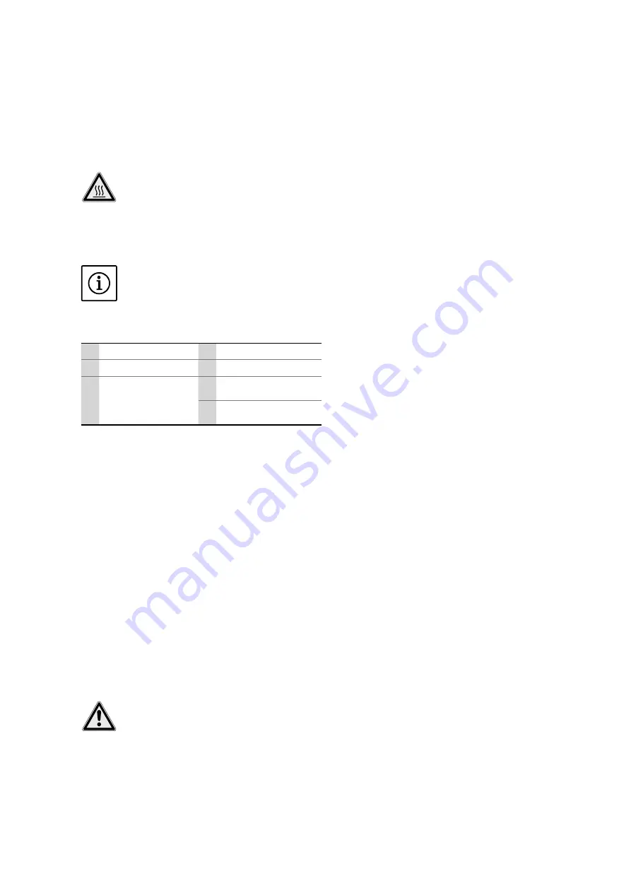
BEWARE of burns! 

The housing parts can heat up to above 

100 °C. There is a risk of burns! After switch

-

ing it off, let the pump cool down to ambient 

temperature.

Discharge pipeline connection

NOTE


The pump is only held in place here by the pip-

ing. All vibrations and torques are transferred to 

the pipe system!

Fig. 2.: Stationary installation 

1 Pump

4 Impact protection plate

2 Discharge pipeline

5 Inlet

3 Non-return valve

6a

Min. water level for im-

mersed operation

6b

Min. water level for 

non-immersed operation

Work steps

1. 

Preparing pumps: about 1 h

• 

Connect the pipe elbow to the pressure port 

using the threaded flange/flange connection.

2. 

Installing the pump: about 1-2 h

• 

Once the pipe elbow has been connected, posi

-

tion the pump at the pressure pipe. If neces-

sary, secure lifting equipment to the pump with 

a shackle, lift the pump and then lower to the 

intended location (sump, pit).

• Screw the pipe elbow onto the existing dis-

charge pipeline.

• Route the power supply cable in such a way 

that it cannot be damaged.

• Have the electrical connections made by a 

qualified electrician.

3. 

Commissioning the pump: about 1-3 h

• 

As described in the “Commissioning” section

Connecting a pressure hose

RISK of pressure hose becoming separated! 

Uncontrolled separation or movement of the 

pressure hose can result in injuries. Secure the 

pressure hose appropriately. Prevent buckling 

of the pressure hose.

Work steps

1. 

Preparing pumps: about 1 h

• 

Fit the pipe elbow to the pressure connection 

using the hose connection.

• 

Fasten the pressure hose to the pipe elbow 

with a hose clip.

2. 

Installing the pump: about 1-2 h

• Position pump in installation location. If neces-

sary, secure lifting equipment to the pump with 

a shackle, lift the pump and then lower to the 

intended location (sump, pit).

• 

Check that the pump is vertical and on a solid 

bearing surface. 

Avoid sinking.

• Route the power supply cable so it cannot be 

damaged.

• Have the electrical connections made by a 

qualified electrician.

• Route the pressure hose so that it is not 

damaged and fasten it at certain points (e.g. 

outflow).

3. 

Commissioning the pump: about 1-3 h

• 

As described in the “Commissioning” section

5.3.3.  Level control

Fill levels can be determined using the level 

control system, meaning the pump is switched on 

and off automatically. The fill level can be record

-

ed using float switches, pressure and ultrasound 

measurements or electrodes.

Note the following information:

• 

When using float switches, ensure that they can 

move freely in the operating area!

• The water level must not fall below the minimum!

• The maximum switching frequency may not be 

exceeded!

• 

If the fill levels fluctuate strongly, then a level 

control should be made on two test points as 

standard. This means larger differential gaps are 

reached.

Installation

For correct installation, please see the installation 

and operation instructions for the level control 

device.

Observe the information on the maximum 

switching frequency and the minimum water 

level!

5.4.  Dry-running protection

To ensure the necessary cooling, the pump must 

be immersed when in operation, depending on 

the operating mode. In addition, make sure that 

no air enters the hydraulics housing.

The pump must therefore always be immersed 

in the fluid up to the top edge of the hydraulic 

housing or, if applicable, up to the top edge of 

the motor housing. For optimum operational 

reliability, we recommend installing a dry-running 

protection system.

Correct running is ensured by float switches or 

electrodes. The float switch or electrode is fixed 

in the sump and switches off the pump when the 

water level falls below the minimum coverage 

level. If the dry-running protection only includes 

one floater or electrode and the fill levels deviate 

significantly, then the pump may turn on and 

off constantly! This can result in the maximum 

Содержание Drain TMT 32M

Страница 1: ... Betriebsanleitung en Installation and operating instructions fr Notice de montage et de mise en service tr Montaj ve kullanma kılavuzu pl Instrukcja montażu i obsługi cs Návod k montáži a obsluze ru Инструкция по монтажу и эксплуатации uk Iнструкція з монтажу та експлуатації ...

Страница 2: ...Fig 2 Fig 4 Fig 3 Fig 1 1 5 6 3 4 2 1 2 3 4 5 6a 6b Tmax 95 C Tmax 75 C W 5 1 2 V 4 U 3 M 3 gn ye L3 L2 21 20 L1 PE 250 V AC 2 5 A cos φ 1 6 DK 1 ...

Страница 3: ...pe of delivery 28 3 7 Accessories 28 4 Transport and storage 28 4 1 Delivery 28 4 2 Transport 28 4 3 Storage 29 4 4 Return delivery 29 5 Installation 29 5 1 General 29 5 2 Installation methods 29 5 3 Installation 30 5 4 Dry running protection 31 5 5 Electrical connection 32 5 6 Motor protection and activation types 33 6 Commissioning 33 6 1 Electrical system 33 6 2 Rotation control 33 6 3 Level co...

Страница 4: ...o make technical modifications to units or components This operating and maintenance manual refers to the pump shown on the title page 1 5 Warranty In general the specifications in the current gen eral terms and conditions apply for the warranty You can find these here www wilo com legal Any deviations must be contractually agreed and shall then be given priority 1 5 1 General The manufacturer is ...

Страница 5: ... When installing or removing the pump never work alone in rooms and sump A second person must always be present The pump must always be switched off before any work is performed on it assembly disman tling maintenance installation The pump must be disconnected from the electrical system and secured against being switched on again All rotating parts must have come to a stop The operator should info...

Страница 6: ... 2 4 Safety and monitoring devices The pumps are equipped with a thermal winding monitor and leakage connection for the motor The pump is switched off if the motor gets too hot during operation or if liquid gets into the motor These devices must be connected by an electri cian and checked to ensure that they function correctly before commissioning Personnel must be informed about the installed sys...

Страница 7: ...ational regulations DANGER explosive fluids It is strictly prohibited to pump explosive flu ids gasoline kerosene etc The pumps are not designed for these fluids The Wilo Drain TMT 32M submersible pumps are designed for intermittent and permanent pump ing of wastewater with solids up to a maximum of 9 mm in sumps and tanks The submersible pumps must not be used for pumping Potable water Fluids con...

Страница 8: ... 20 h Maximum 50 h Cable Type TGSH J Size 7G1 5 Length 10 m Fluid temperature T Immersed 3 95 C 37 203 F Non immersed 3 75 C 37 167 F 3 5 Type key Example Wilo Drain TMT 32M113 7 5Ci TM Tauchmotorpumpe submersible pump T Pumping of wastewater 32 Pressure connection G 1 DN 32 M Half open multi channel impeller 113 Impeller diameter in mm 7 5 10 rated power P2 in kW Ci Material version Cast iron 3 6...

Страница 9: ...oating fulfils its intended purpose Please note that elastomer parts and coatings become brittle over time If the product is to be stored for longer than 6 months we recommend checking these parts and replacing them as nec essary Consult the manufacturer for details 4 4 Return delivery Pumps that are returned to the factory must be properly packaged This means that impurities have been removed fro...

Страница 10: ...s stability and strength If the motor housing is to be taken out of the fluid during operation the operating mode for non immersed operation should be followed To keep dry motors sufficiently cooled in S3 mode they must be flooded completely before being switched back on if the motor has been taken out of the fluid Never let the pump run dry The water level must never fall below the minimum Theref...

Страница 11: ...nstallation location If neces sary secure lifting equipment to the pump with a shackle lift the pump and then lower to the intended location sump pit Check that the pump is vertical and on a solid bearing surface Avoid sinking Route the power supply cable so it cannot be damaged Have the electrical connections made by a qualified electrician Route the pressure hose so that it is not damaged and fa...

Страница 12: ...ice RCD Switchgears must be purchased as accessories 5 5 1 Mains fuses The back up fuse must be rated according to the starting current You will find the starting current on the rating plate Only slow blow fuses or K characteristic auto matic cut outs may be used as a back up fuse 5 5 2 Checking the insulation resistance and moni toring devices before commissioning If the values measured deviate f...

Страница 13: ...ating mode Minimum water submersion max immersion depth These general conditions must also be checked after a lengthy period without operation and any defects detected must be repaired Always keep this manual either by the pump or in a place specially reserved for it where it is accessible for the entire operating personnel at all times In order to prevent damage or serious injury when commissioni...

Страница 14: ...ecked for wet well installation Clean the pump sump of coarse contaminants Open all slide valves on the pressure side 6 4 2 Switching on off The pump is switched on and off using a sepa rate operating point on off switch switchgear provided by the customer During the start up procedure the rated current is temporarily exceeded After the start up pro cedure is finished the current must not exceed t...

Страница 15: ...uitable lifting device may be required to do this 7 4 Return delivery storage For shipping the parts must be packed in tear proof plastic bags of sufficient size in such a manner that they are tightly sealed and leak proof For return delivery and storage please also refer to the Transport and storage section 7 5 Disposal 7 5 1 Operating materials Oils and lubricants must be collected in appropri a...

Страница 16: ... per forming maintenance and repair work This must also be disposed of properly 8 1 Operating materials 8 1 1 Overview of white oil The sealing chamber is filled with white oil that is potentially biodegradable When changing the oil we recommend the fol lowing oil types Aral Autin PL Shell ONDINA 919 Esso MARCOL 52 or 82 BP WHITEMORE WOM 14 Texaco Pharmaceutical 30 or 40 All oil types marked with ...

Страница 17: ...for the monitoring equip ment has to be disconnected in the switchgear The monitoring equipment can then be checked with an ohmmeter The following values should be measured Bimetallic strip Value 0 passage If there are larger deviations consult the manu facturer 8 3 5 Inspection of the switchgear relays used See the relevant installation and operating in structions for a description of the individ...

Страница 18: ... fluid available Open inlet for tank or slide valve 2 Intake blocked Clean the supply line slide valve suction piece suction port or suction strainer 3 Impeller blocked or slowed Switch off pump secure it against being switched back on again and free the impeller 4 Faulty hose piping Replace defective parts 5 Intermittent operation Check switching system Fault The unit runs but not within the spec...

Страница 19: ...mer Service On site support from Wilo customer service Inspection or repair of the pump at the factory Please note that you may be charged for some services provided by our customer service For more details please contact Wilo customer service 10 Appendix 10 1 Spare parts Spare parts can be ordered from Wilo customer service To avoid return queries and incorrect or ders the serial and or article n...

Страница 20: ...Pioneering for You WILO SE Nortkirchenstraße 100 44263 Dortmund Germany T 49 0 231 4102 0 F 49 0 231 4102 7363 wilo wilo com www wilo com ...

Отзывы: