11
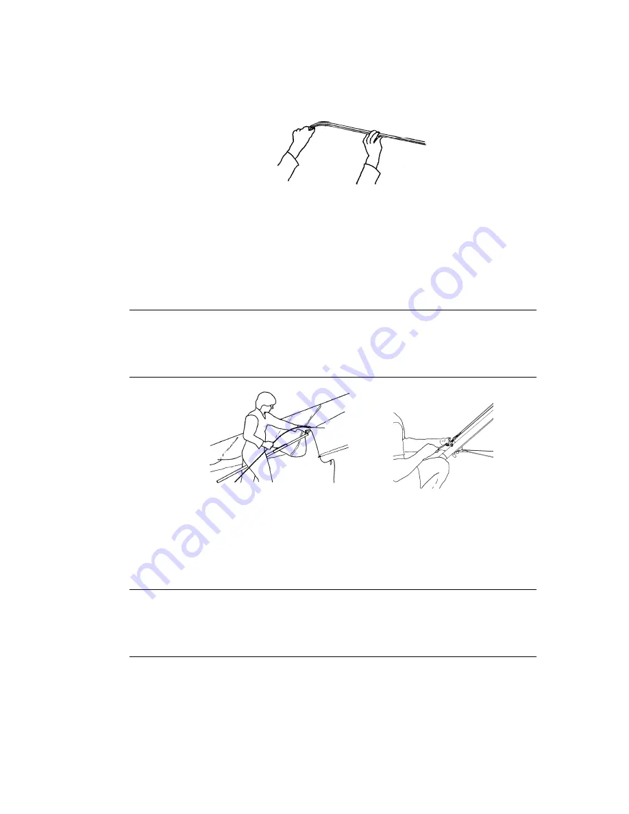
7. Remove the battens from the batten bag, and check each batten for symmetry against the corre-
sponding batten from the other wing. Wills Wing convention is that black tipped battens go in the
right wing and white tipped battens in the left, except for the straight #1 plug on battens which all
have black tips.
8. Install the cambered top surface battens in the sail, leaving out the shortest two on each side (#2
and #3) for now. Each batten is secured by a double loop of the batten string. Order of insertion is
longest to shortest, from the root out. When inserting the inboard most battens, lift the keel to ease
the insertion. The longest battens may catch the edge of the mylar insert at the front of the sail. If
that happens, make sure that the mylar insert is not creased or folded in the pocket. When these
battens reach the back side of the leading edge tube, it may be necessary to lift the sail along the
batten pocket to facilitate insertion of the batten all the way.
Insert the battens carefully, so as to minimize stress and wear on the sail. Never insert or
remove top surface battens with the crossbar tensioned (except for up to the last four on
each side) and never insert or remove battens with heavy wind pressure on the top of the
sail or in any condition which causes the battens to slide with great resistance in the pockets.
9. Spread the wings all the way and check all cables for any twisted thimbles or tangled cables.
10. At the rear of the keel, tension the crossbar and secure the crossbar sweep wire by pulling the
keyhole channel aft along the keel until the large hole lines up with the keyhole bolt. Lower the
keyhole bracket over the bolt until the channel can slide forward so that the narrow part of the
keyhole slot is fully captive in the narrow part of the bolt collar.
Never install the keyhole channel onto the keyhole bolt without making absolutely sure
that the channel is fully engaged on the narrow neck of the bolt, and tensioned forward
into the fully locked position. An in-flight disengagement of this attachment will cause a
complete loss of structural support of the glider and a total loss of control.
11. Overlap the mating velcro surfaces of the front keel pocket around the bottom of the keel tube and
secure them together. The VG activation rope should be inside the keel pocket.
Содержание Fusion 141
Страница 1: ...Fusion 141 and 150 Owner Service Manual October 15 1998 Third Edition ...
Страница 2: ......
Страница 6: ......
Страница 8: ......
Страница 52: ... 44 ...
Страница 63: ...Phone 714 998 6359 Fax 714 998 0647 Page A 11 Fusion Assembly Diagrams October 1998 80E08 VG Control Bar ...
Страница 65: ...Phone 714 998 6359 Fax 714 998 0647 Page A 13 Fusion Assembly Diagrams October 1998 Fusion 141 Frame Plans ...
Страница 67: ...Phone 714 998 6359 Fax 714 998 0647 Page A 15 Fusion Assembly Diagrams October 1998 Fusion Control Bar ...
Страница 68: ...Wills Wing 500 West Blueridge Orange CA 92865 Page A 16 Fusion Assembly Diagrams October 1998 ...


