Page 12
Installer’s Information Manual
You must connect furnace to a listed chimney or vent
complying with a recognized standard or a suitably sized,
constructed and lined masonry chimney. Chimney lining
method and material must comply with local requirements.
Use corrosion-resistant material meeting nationally
recognized standards for vent construction.
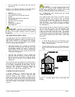
This furnace must not vent into an unlined-masonry
chimney or an unlined-concrete chimney and must not
single appliance vent into a tile-lined chimney. However,
this furnace may be common vented into a tile-lined
masonry chimney provided (1) the chimney is currently
serving at least one drafthood equipped appliance and (2)
the vent connectors and chimney are sized in accordance
with the appropriate vent table.
WARNING
: Select appropriate venting materials
and clearances. Inadequate vent or chimney could allow
combustion products to collect in building, resulting in fire,
nausea or death by asphyxiation.
WARNING
: Do not use unlined masonry
chimneys. These increase risk of condensate formation,
which may cause chimney to deteriorate, allowing
combustion products and condensate to collect in building.
Multistory and common venting with other Category I
appliances is permitted. The venting system must be in
accordance with the National Fuel Gas Code ANSI
Z223.1/NFPA 54 and/or current CAN/CGA B149 Installation
Codes, local codes and approved engineering practices.
Vent this furnace separately from any appliance designed
to burn solid fuel, such as wood or coal. If a fireplace
chimney flue is used to vent this appliance, the fireplace
opening must be permanently sealed.
Avoid over-sizing furnace for your application. Select a
furnace model with a rated heating output close to the
calculated heating load. This extends the firing period,
decreasing the potential for condensate formation in the
vent.
The designer must consider the building's orientation,
answering two questions: Will the vent terminate outside
the building where its operation could be adversely affected
by winds? Could any adjacent buildings adversely affect
vent operation? Allowing for these factors can reduce the
possibility of down draft conditions.
If your local experience indicates possible condensation
problems, provide for draining and disposal of venting
system condensate.
VENT SIZING AND INSTALLATION
Proper vent size can be determined from these instructions
and "Venting Tables For Category I Venting" included as an
addendum to these instructions, the National Fuel Gas
Code ANSI Z223.1/NFPA 54 and/or current CAN/CGA
B149 Installation Codes. Venting tables include instructions
for single appliance venting and multiple appliance
(common) venting.
Refer to venting tables for correct size vent. An undersized
vent cannot adequately carry all combustion products
outdoors. An oversized vent will not heat up rapidly enough
to avoid condensation.
Vents and chimneys usually extend vertically with offsets
not exceeding 45 degrees from vertical. Consider vent pipe
runs more than 45 degrees from vertical as horizontal runs.
Include their length in the total horizontal run.
Vent height must be a minimum of five feet for Category I
vent systems. Minimize vent connector horizontal runs to
the extent possible for best performance. Horizontal
portions of the venting system must be supported at each
joint using hinges, straps or equivalent to prevent sagging.
Slope horizontal portions upward from furnace at least 1/4
inch per foot.
Sometimes the horizontal distance from the furnace to the
vent or chimney is already given. This is known as the
horizontal vent connector run. The vent or chimney height
is also usually given as is the Btu per hour input of the gas
appliances served by the vent. Check these parameters to
be sure the venting system will work. Use venting
addendum, these instructions, part 7 of current National
Fuel Gas Code ANSI Z223.1/NFPA 54 and/or CAN/CGA
B149 Installation Codes. Use vent capacity tables in
venting addendum to check existing or new vent sizes for
Category I furnaces.
Install vent materials following their listing terms,
manufacturer's instructions, these instructions and local
codes.
A gas vent passing through a roof must extend through roof
flashing, jack or thimble. It must terminate above roof
surface.
Designer and installer must provide an appropriately sized
common vent for all appliances connected to it. See
venting addendum for single appliance venting and multiple
appliance (common) venting. For multistory installations,
refer to current National Fuel Gas Code ANSI Z223.1/NFPA
54 and/or CAN/CGA B149 Installation Codes.
VENT CONNECTORS
Vent connectors must be made of listed single-wall or Type
B double-wall components. They must be thick enough to
withstand physical damage and be readily accessible for
inspection, cleaning and replacement.
Use Type B vent connectors in or through attics, crawl
spaces, or other cold areas. Install thimbles that meet local
codes when vent connectors pass through walls or
partitions of combustible material.
Keep vent connectors as short as possible by locating
furnace as close as practical to vent or chimney. Avoid
unnecessary turns or bends that create resistance to flow of
vent gases. Adding an elbow adds resistance.
You may increase vent connector diameter to overcome
installation limitations and obtain connector capacity equal
to furnace input. Make this increase as close as possible to
furnace vent collar, allowing for necessary adapters and
fittings. Do not increase vent size more than two sizes


