Installer’s Information Manual
Page 5
Provide ample space for servicing and cleaning, and
around air openings into the combustion chamber.
Location must allow 30 inches minimum front clearance for
service.
You may install furnace on non-combustible flooring or for
upflow or horizontal installations on wood flooring. A
combustible floor base, available from the manufacturer, is
required for downflow furnace installation on wood flooring.
See Section 5, "Allowing For Clearances."
Install the furnace so all electrical components are
protected from water.
Install the furnace level.
When the furnace is in a repair garage or inside the heated
space, exhaust fans can adversely affect its operation.
Exhaust fans in kitchen, bathrooms, clothes dryers or
anywhere within heated space increase combustion and
ventilation air requirements. This is because exhaust fans
reduce the amount of combustion and ventilation air
available to the furnace. A fireplace also reduces amount
of combustion and ventilation air.
WARNING
: You must allow for these reductions
or there could be inadequate combustion and ventilation
air. This could cause nausea, death by asphyxiation, or
fire.
Sufficient air must be provided to ensure there will not be a
negative pressure in furnace room or space. In addition,
there must be a positive seal between furnace and return
air duct to avoid pulling air from burner area.
When a cooling unit is installed with this furnace, the
furnace must be installed on the upstream side of the
cooling unit to avoid condensation in the furnace heat
exchanger.
When furnace is in a residential garage, it must be installed
so that the main burners are located no less than 18 inches
above the floor. Also, furnace should be protected from
physical damage by vehicles.
When furnace is in a public garage, airplane hanger, or
other building having hazardous atmosphere, install unit in
accordance with recommended good practice requirements
of the National Fire Protection Association, Inc. Consult
local code authorities for additional location requirements.
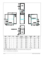
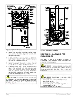
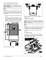
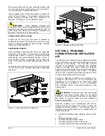
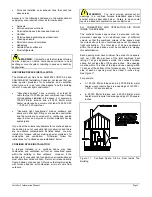
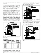
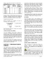
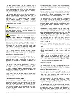
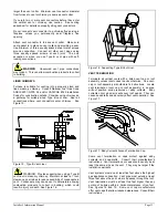
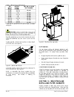
See Figure 3 for dimensions and specifications.
SECTION 4. CONVERSION TO
DOWNFLOW CONFIGURATION
Most furnaces are shipped from the factory in the upflow
configuration with the vent collar extending out through the
top plate at the supply end of the furnace. In this
configuration, the furnace can be installed as an upflow
furnace or as a horizontal furnace on its left or right side.
In the downflow configuration, the inducer assembly is
repositioned - locating the vent collar inside the furnace
vestibule near the manifold pipe. In this configuration the
furnace can be installed as a downflow furnace or as a
horizontal furnace on its left or right side.
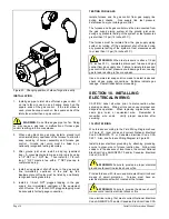
Before starting the conversion, lay the furnace on its back
with the front door removed. Read the following
instructions all the way through and study the components
described. See Figure 4 for component identification and
location.
NOTE: If possible, decide on direction of gas entry now,
because the screws to change direction of the furnace gas-
control-inlet elbow are accessible during this conversion.
See Section 9, "Installing Gas Piping."
1. Remove the two junction box mounting screws and the
four top plate mounting screws. Save all screws.
Remove the top plate and front duct flange.
2. Disconnect pressure switch wires and inducer motor.
3. Remove and save ten screws from the inducer pan.
Do not drop screws into heat exchanger openings.
4. Lift inducer/pan assembly about 1/4 inch and tilt left
side up to clear top casing flanges.
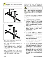
5. Rotate inducer/pan assembly 180 degrees as shown in
Figure 5. Line up mounting holes and replace the ten
screws in inducer pan.
6. If nessessary, remove wire tie(s) from the excess
length of the wire harness containing the pressure
switch wires (blue and purple).
7. Re-connect pressure switch wires as follows. (Wires
are numbered on insulation near terminals).
a) Purple wire (#6) to pressure switch common
(C) terminal.
b) Blue wire (#5) to pressure switch normally
open (NO) terminal.
c) Route pressure switch wires around inducer
motor and away from hot flue box.
8. Re-connect inducer motor.
9. Replace wire tie in the same area such that wires do
not touch hot flue box or inducer pan.
10. Remove and save the four screws that secure base
panel to casing sides. Remove base panel.
11. Install top plate removed in step 1 in place of the base
panel. Secure with four screws. Vent collar is now
lined up with vent outlet hole in top plate.


