background image

P

OSITION

I

T  

PI-150

 AND 

PI-75


7-10 


TP-5129001-J 


January 2022 


PositionIT Wiring Diagram 

120/240 VAC Application 

Sheet 3 of 4 

Drawing: WD-50610 

Содержание 5061001

Страница 1: ...PI 150 P N 5061001 AND PI 75 P N 5191201 OPERATOR S MANUAL PI 150 shown The Will Burt Company 401 Collins Blvd Orrville OH 44667 www willburt com TP 5129001 J January 2022 2022 The Will Burt Company ...

Страница 2: ......

Страница 3: ... NO EMPLOYEE DISTRIBUTOR OR REPRESENTATIVE IS AUTHORIZED TO CHANGE THIS WARRANTY IN ANY WAY OR GRANT ANY OTHER WARRANTY ON BEHALF OF WILL BURT Claims for defects in material and workmanship shall be made in writing to Will Burt within thirty 30 days of the discovery of defect Failure to provide notice as required hereby shall be conclusive evidence that the product was in conformity with the warra...

Страница 4: ...01 B August 11 2015 Added Section 6 Updated sections 1 4 1 6 3 3 3 4 and Section 7 Minor formatting changes throughout manual TP 5219001 C March 21 2016 Updated sections 1 4 1 6 1 1 6 3 1 6 6 2 6 2 3 3 4 2 3 4 3 5 6 1 6 2 and 7 Updated Table 3 2 and Table 3 3 Minor formatting changing throughout manual TP 5219001 D July 22 2016 Updated Section 2 1 TP 5219001 E November 21 2016 Updated Sections 3 3...

Страница 5: ... 2 2 Installation Tools 2 2 2 3 Components 2 2 2 4 Unpacking 2 2 2 5 Mounting the Positioner 2 3 2 6 Wiring the System 2 4 2 6 1 Positioner Plugs 2 4 2 6 2 Connecting Power and Controls 2 8 2 7 Mounting the Payload 2 12 2 8 Setting Presets and Electronic Limit Stops 2 13 Section 3 Operation 3 1 3 1 Pre Operation Check 3 1 3 2 Operation Tools 3 2 3 3 General Controls 3 2 3 3 1 Keyboard 3 3 3 3 2 Jo...

Страница 6: ...ions PI 150 Shown 1 3 Figure 1 3 Positioners 1 5 Figure 1 4 Default Joystick Controller 1 6 Figure 1 5 Power Data Cable 1 7 Figure 1 6 Positioner Power Supply 1 8 Figure 1 7 Step Up Converter 1 8 Figure 1 8 Step Down Converter 1 9 Figure 1 9 Barrel Connector 1 9 Figure 2 1 Rear of Positioner PI 150 Shown 2 3 Figure 2 2 Positioner Mounting Hole Pattern 2 3 Figure 2 3 Positioner Plug Locations PI 15...

Страница 7: ...igure 6 2 Panel Mount Controller P N 4270601 6 4 Table of Tables Table 1 1 Positioner Specifications 1 4 Table 1 2 Default Joystick Controller P N 5098901 Specifications 1 4 Table 1 3 Standard Cables 1 7 Table 2 1 Tools and Materials Recommended for Installation 2 2 Table 3 1 Tools and Materials Recommended for Operation 3 2 Table 3 2 Limit Stop Adjustment Numbers 3 6 Table 3 3 Default Limit Stop ...

Страница 8: ...POSITIONIT PI 150 AND PI 75 vi TP 5129001 J January 2022 ...

Страница 9: ...recautions that are not related to any specific procedures These are recommended precautions that personnel must understand and apply throughout installation operation maintenance and troubleshooting Additional precautions which apply to specific procedures and steps may be listed with the procedure or step to which they apply Electrocution Hazard Do not touch live wires Make sure all power has be...

Страница 10: ...jury could result if proper installation inspection operation and maintenance procedures are not observed Lifting Hazard Manually lifting over 55 lb 25kg is prohibited In the UK all lifting equipment must be thoroughly examined annually by a competent person according to the Lifting Operations and Lift Equipment Regulations 1998 Equivalent regulations exist in other EU states Safety Instruction Re...

Страница 11: ... mast This manual covers the following models of PositionIt PI 150 P N 5061001 PI 75 P N 5191201 The PositionIt does not currently support the following GPS Control Infrared Remote Control RS 232 GUI Interface customer supplied only Mast Up Down Control 1 1 Safety Precautions Refer to the Safety Summary for precautions to be observed while installing operating maintaining or troubleshooting this e...

Страница 12: ...d controller system Payload refers to the object or equipment being moved by the positioner Positions Home Figure 1 1 to refer to the factory set preset position 0 zero which is set to move the positioner to the mid point of both the pan and tilt In this position the tilt platform will be horizontal and the pan axis will be in the center position In this position the rear of the positioner is the ...

Страница 13: ...wn View Figure 1 2 Positioner Directions PI 150 Shown When using the default joystick o Pushing the joystick forward will tilt the positioner towards the rear o Pulling the joystick back will tilt the positioner towards the front o Moving the joystick to the right will rotate the joystick clockwise o Moving the joystick to the left will rotate the joystick counterclockwise Symbols Characters insid...

Страница 14: ...grees of Rotation 200 Tilt Degrees of Rotation 90 Pan Speed 6 5 second Tilt Speed 5 5 second Backlash 0 15 Repeatability 0 3 Maximum Continuous Power 44 W Maximum Continuous Current 1 85 amps Input Voltage 24 VDC Protocol Pelco D used Pelco P available Ingress Protection Rating IP68 Baud Rate 2 400 bps Table 1 2 Default Joystick Controller P N 5098901 Specifications Specifications Input Voltage 12...

Страница 15: ...asing Uses stainless steel fasteners Has weather and dust proofing to an IP68 rating Is designed to minimize backlash Is configured to run on RS485 data using Pelco D protocol Contains an internal tether to prevent the pan and tilt head from separating from the mast in the event of an impact load separating the pan and tilt head from the base Ships with the PositionIt PI 150 and PI 75 Operator s M...

Страница 16: ...e Has a joystick LCD Screen and a keyboard Has programmable presets Has programmable electronic limits Has speed control Ships with the controller manual Is not designed to handle inclement weather and should be kept in a protected environment Figure 1 4 Default Joystick Controller Left With Keyboard Cover On Right With Keyboard Cover Off Joystick LCD Screen Keyboard Keyboard Cover ...

Страница 17: ...er end to allow for a Nycoil pull The end with the loose wires can be cut if the customer requires a shorter length Figure 1 5 Power Data Cable Table 1 3 provides the part numbers for the standard cables Table 1 3 Standard Cables Will Burt Part Number Length 5611601 35 ft 10 m 5611602 66 ft 20 m 5611603 99 ft 30 m Alternatively the 90 elbow connector P N 213227 PT08E 14 5S SR may be purchased sepa...

Страница 18: ...wer to 24 VDC input power for the positioner The power supply has short circuit overcurrent overvoltage and over temperature protections It is an IP67 design and is suitable for dry damp or wet locations Figure 1 6 Positioner Power Supply 1 6 5 Step Up Converter The step up converter P N 208012 Figure 1 7 is used in systems with 12 VDC input power to step up the power to 24 VDC for the positioner ...

Страница 19: ...step down the power to 12 VDC to power the default joystick controller if the AC power supply supplied with the joystick is not used to provide power Figure 1 8 Step Down Converter 1 6 7 Barrel Connector 2 1 mm The 2 1 mm barrel connector P N 5195601 Figure 1 9 can be used to connect the controller to the step down converter or 12 VDC power source Figure 1 9 Barrel Connector ...

Страница 20: ...g to the schematic Section 7 See Section 2 6 for additional detail 3 Mount the payload with appropriate hardware See Section 2 7 for additional detail To operate the positioner Section 3 1 Attach the controller 2 Operate the positioner using the controller See Section 3 for additional detail on the function of the default joystick controller P N 5098901 3 If required see Section 3 3 4 for informat...

Страница 21: ...l size and wind speed Mounting the system to a structure unable to resist the forces generated from customer specific loading scenario could result in death or serious injury and could damage the system Safety Instruction Mounting Instructions Be sure to understand all mounting instructions The mounting hardware must include proper means to resist vibration loosening such as thread locking compoun...

Страница 22: ...es will vary based upon your order Possible components include Positioner PI 150 or PI 75 Controller Controller Manual ships with controller PositionIt PI 150 and PI 75 Operator s Manual this manual Power Data Cable used to connect positioner to the controller and the power supply Some combination of the following o Positioner Power Supply used in systems with AC input power o Step Up Converter us...

Страница 23: ... full pan and tilt movement Have the positioner base face down Do not mount the positioner upside down Be sure to take into consideration other external factors such as wind or ice loading when selecting a mounting location Make sure that these external factors do not overload the system Reference Figure 2 2 for the mounting hole locations for the system There are 4 holes equally spaced Connect th...

Страница 24: ...ttom egress on the mounting pedestal ships from the factory with a plug plate installed To use the bottom egress the plug plate and the removable plug must be swapped If either egress is not properly sealed the positioner will leak and become damaged voiding the warranty Side Egress with Removable Plug View From Side Bottom Egress with Plug Plate View From Beneath Figure 2 3 Positioner Plug Locati...

Страница 25: ...l out the attached wires and gasket behind it Figure 2 4 Figure 2 4 Carefully Pull Out the Removable Plug Gasket and Attached Wires 4 Disconnect the wires from the positioner The wires are connected to the positioner with a quick connect Figure 2 5 Figure 2 5 Quick Connect Plug Connector Gasket Wires Quick Connect ...

Страница 26: ... the plug plate to the bottom of the mounting pedestal Figure 2 6 Figure 2 6 Remove the 4 Bolts Securing the Plug Plate 6 Remove the plug plate and the gasket behind it Figure 2 7 Set the gasket and plug plate aside Figure 2 7 Remove Plug Plate and Gasket Plug Plate Gasket Plug Plate Bolt ...

Страница 27: ...ck connect between the wires from the positioner and the plug making sure the gasket is in place 9 Gently push the wires into the positioner and secure the gasket and removable plug in place at the bottom of the mounting pedestal Figure 2 9 If the gasket is not properly installed the positioner will leak and become damaged voiding the warranty Figure 2 9 Secure the Gasket and Removable Plug to the...

Страница 28: ...ed voiding the warranty 2 6 2 Connecting Power and Controls This section describes how to connect the power and controls to the system Equipment Damage Ensure the connections are made properly to prevent water ingress into the positioner through the connections Should water enter the positioner extreme problems can occur Depending on the configuration of your system power and controls can be hooke...

Страница 29: ... power data cable to the step up converter 6 Run the 12 VDC power to the controller and the step up converter Run a 5 amp slow blow fuse customer supplied inline between the power supply and the controller and step up converter An optional DC cable connector may be used to connect the controller and the power supply Powered with 24 VDC The default joystick controller P N 5098901 runs on 12 VDC pow...

Страница 30: ...ptional DC to DC converter can be run inline between the power supply and the positioner to help maintain 24 VDC under low voltage situations Powered with 120 VAC 50 or 60 Hz or 240 VAC 50 or 60 Hz The positioner runs on 24 VDC and power other than 24 VDC must be converted to 24 VDC for the positioner The default joystick controller P N 5098901 comes with its own power supply for the VAC input whi...

Страница 31: ... green data A and white data B wires from the power data cable to the controller 5 Wire the 16 AWG red power and black ground wires from the power data cable and the controller to the positioner power supply Run a 2 amp slow blow fuse customer supplied inline between the positioner power supply and the positioner and controller An optional step down converter can be run between the controller and ...

Страница 32: ...r unable to resist the forces generated from the customer specific loading scenario could result in death or serious injury and could damage the positioner To attach the payload 1 Ensure power to the system is off while installing the payload 2 Reference the mounting hole patterns for the payload Figure 2 14 PI 150 Payload Mounting Hole Pattern Figure 2 15 PI 75 Payload Mounting Hole Pattern 3 Pos...

Страница 33: ...e Pattern 2 8 Setting Presets and Electronic Limit Stops As part of the installation process the operator may wish to set preset positions or adjust the electronic limit stops For information on how to do this see Section 3 3 4 for setting presets Section 3 3 5 for adjusting electronic limit stops ...

Страница 34: ...POSITIONIT PI 150 AND PI 75 2 14 TP 5129001 J January 2022 ...

Страница 35: ...propriately connected Ensure that the following warnings are understood and followed Tip Over Hazard Do not operate in high winds Operate on level ground only Stand clear of positioner and payload during operation Be certain positioner is level and secure System tip over could result in death or serious injury Safety Instruction Operation For outdoor use only Do not use in areas that have been cla...

Страница 36: ...troller P N 5098901 for the system Refer to the controller manual for information on the specific controller with your system Some functions of the default joystick controller are not used with the positioner The default joystick controller is not designed to handle inclement weather and should be kept in a protected environment When the controller is in operation the LCD screen backlight will tur...

Страница 37: ...the CamID Prev previous which is used when using the menu to save preset positions and to cancel out of a preset without recalling it N where N represents a number on the keyboard which is used to access menu functions and as part of the processes to store and recall presets Figure 3 1 Keyboard Keys 3 3 2 Joystick The joystick pans and tilts the positioner The speed of the movement will directly r...

Страница 38: ...t is possible to simultaneously adjust both the pan and tilt of the positioner by moving the joystick towards a diagonal Arrows for both applicable directions will appear on the LCD screen For example when tilting forward and panning right both an arrow pointing forward and an arrow pointing right will appear The positioner will continue to move in the direction given by the joystick until the joy...

Страница 39: ...ioner to the desired position for the preset 2 Press Set 3 Press N where N represents the number being assigned to the preset position 4 Press Pre The preset position is stored 3 3 4 2 Recalling Presets with the Keyboard The preferred way to recall a preset position is with the keyboard as moving the joystick while in the menu will not stop the motion of the positioner e g if an emergency stop is ...

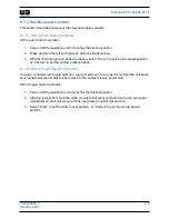
Страница 40: ...assis connector or positioner body This will cause damage to the positioner to occur 3 3 5 1 Adjust Limit Stops with the Keyboard To adjust the electronic limit stops with the keyboard 1 Use the joystick to drive the positioner to the desired electronic limit stop 2 Press Set 3 Press N where N represents the number which corresponds to the preset being adjusted Reference Table 3 2 to determine whi...

Страница 41: ...Restores default up limit 73 Restores default down limit 3 Press Pre The electronic limit has been adjusted back to the factory default 3 4 Unstowing the Positioner The customer must set preset position 2 before this function can be used To unstow the positioner 1 Power on the system 2 Perform the pre operation check Section 3 1 3 Press 2 4 Press Pre The positioner will move to the preset unstowed...

Страница 42: ...he stowed position the positioner will first pan and then tilt As the positioner nears the stowed position it will slow down If an emergency stop is required as the positioner is moving to position move the joystick to cancel out the command The system is stowed 4 Power down the system 3 6 Transportation Before transporting the system the system needs to be secured Do not transport without the pos...

Страница 43: ...t to ensure all fixings and fastenings are tight All fixings and fastenings must be thoroughly checked for tightness 1 month following installation and thereafter at regular 6 month intervals Inspect to ensure cables are undamaged and properly terminated Cabling of the correct type as specified by national and local standards should be used Cables should be checked for wear at 6 month intervals an...

Страница 44: ...POSITIONIT PI 150 AND PI 75 4 2 TP 5129001 J January 2022 ...

Страница 45: ...or tilt in a single direction An electronic limit stop has been reached Reset the electronic limit stops Section 3 3 5 Positioner does not pan or tilt in multiple directions The system is not receiving power Check the schematics Section 7 The power supply is wrong Check the schematics Section 7 System settings are incorrect Reset the factory defaults Section 5 2 The controller is in a menu Exit th...

Страница 46: ...least 2 seconds Stuck in Controller Menu While in menu functions the operator cannot exit a menu The method to exit individual menus varies Move the joystick to the left to back out of the menu Press the Prev button to back out of the menu Look for an Exit menu option Select that option Disconnect and reconnect power to the controller The Controller Display is Off The controller display is off The...

Страница 47: ... d Baudrate 2400 Figure 5 1 Start Up Screen To reset these settings proceed as follows 5 2 1 CamID When the controller is powered on the CamID will be displayed The CamID should be 001 If necessary reset the CamID to 001 To reset the CamID 1 From the start up screen Figure 5 1 press 1 2 Press Cam The CamID will change to 001 The setting is saved 5 2 2 MonID When the controller is powered on the Mo...

Страница 48: ...appear Figure 5 2 1 Keyboard setup 2 Dome setup 3 Protocol setup 4 Exit menu Figure 5 2 Menu Screen 2 Navigate to Protocol setup and move the joystick to the right to go to the submenu The Protocol setup screen will appear Figure 5 3 1 Quad DVR 2 Dome Figure 5 3 Protocol Setup Screen 3 Navigate to Dome and move the joystick to the right to go to the submenu The Dome screen will appear Figure 5 4 1...

Страница 49: ...e the joystick right To reset the baud rate 1 Press Menu for 2 seconds The Menu screen will appear Figure 5 2 2 While remaining on Keyboard setup move the joystick to the right to go to the submenu The Keyboard setup screen Figure 5 5 will appear The number beside 2 Set baudrate may vary 1 Set KB ID 1 64 2 Set baudrate 2400 3 Joy calibrate 4 About Keyboard Figure 5 5 Keyboard Setup Screen 3 Naviga...

Страница 50: ...POSITIONIT PI 150 AND PI 75 5 6 TP 5129001 J January 2022 ...

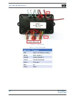
Страница 51: ...trol Assembly P N 4270601 section 6 2 Toggle Switches Push Buttons These controls are wired into J11 Figure 6 1 6 1 1 Electrical Connections The electrical connections are as follows Figure 6 1 J3 Board Power J11 Discrete Inputs active high contact closure 6 1 2 Wire the Bridge Board Interface The bridge board interface operates from 10 33 VDC however the positioner requires 24 VDC for proper oper...

Страница 52: ...nuary 2022 Figure 6 1 Contact Closure Table 6 1 Contact Closure Wires Wire Color Function Red Power 24 VDC to switch Brown Stow preset 1 Orange Unstow preset 2 Yellow Counter Clockwise Green Clockwise Blue Up Violet Down Contact Closure Wires J11 J3 ...

Страница 53: ...preset position or Unstow to set the unstow preset position 6 1 3 2 With a Toggle Switch Controller If using a controller with toggle switches a jumper will need to be used to connect the clockwise and counterclockwise contact closure wires to the contact closure power wire With a toggle switch controller 1 Pan and tilt the positioner until it reaches the desired position 2 Attach a jumper from bo...

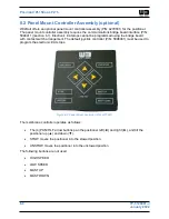
Страница 54: ...ot be programmed using the bridge board with contact switch arrangement The default joystick controller P N 5098901 must be used to program the electronic limit stops Figure 6 2 Panel Mount Controller P N 4270601 The membrane controller operates as follows The 4 PAN TILT arrow buttons pan the positioner left and right and tilt the positioner up and down STOW moves the positioner into the stowed po...

Страница 55: ...POSITIONIT PI 150 AND PI 75 TP 5129001 J 7 1 January 2022 Section 7 Drawings This section contains drawings of the system ...

Страница 56: ...POSITIONIT PI 150 AND PI 75 7 2 TP 5129001 J January 2022 ...

Страница 57: ...POSITIONIT PI 150 AND PI 75 TP 5129001 J 7 1 January 2022 ...

Страница 58: ...POSITIONIT PI 150 AND PI 75 7 2 TP 5129001 J January 2022 POSITION IT 100 FT LB POSITIONER 24 V BLK Drawing 50610 ...

Страница 59: ...POSITIONIT PI 150 AND PI 75 TP 5129001 J 7 3 January 2022 ...

Страница 60: ...POSITIONIT PI 150 AND PI 75 7 4 TP 5129001 J January 2022 POSITION IT 50 FT LB POSITIONER 24 V BLK Drawing 51912 ...

Страница 61: ...POSITIONIT PI 150 AND PI 75 TP 5129001 J 7 5 January 2022 ...

Страница 62: ...POSITIONIT PI 150 AND PI 75 7 6 TP 5129001 J January 2022 PositionIT Wiring Diagram 12 VDC Application Sheet 1 of 4 Drawing WD 50610 ...

Страница 63: ...POSITIONIT PI 150 AND PI 75 TP 5129001 J 7 7 January 2022 ...

Страница 64: ...POSITIONIT PI 150 AND PI 75 7 8 TP 5129001 J January 2022 PositionIT Wiring Diagram 24 VDC Application Sheet 2 of 4 Drawing WD 50610 ...

Страница 65: ...POSITIONIT PI 150 AND PI 75 TP 5129001 J 7 9 January 2022 ...

Страница 66: ...POSITIONIT PI 150 AND PI 75 7 10 TP 5129001 J January 2022 PositionIT Wiring Diagram 120 240 VAC Application Sheet 3 of 4 Drawing WD 50610 ...

Страница 67: ...POSITIONIT PI 150 AND PI 75 TP 5129001 J 7 11 January 2022 ...

Страница 68: ...POSITIONIT PI 150 AND PI 75 7 12 TP 5129001 J January 2022 PositionIT Wiring Diagram Communications Bridge Board Sheet 4 of 4 Drawing WD 50610 ...

Отзывы: