background image

© Wikora GmbH 

Page 9  

                      Status: 27.04.2015 


                                                                                                                                                                       Errors excepted.        


3.3.2 Alignment and installation 


3.3.2.1 In general 


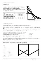
The  collectors  should  be  aligned  southward  and  show  an  ideal  angle 
according  to  latitude  and  application.    The  mounting  frame  can  be 
installed  with  different  angles  (30/45/60°).  In  addition,  a  variable  angle 
adjustment between 30 and 60° can be carried out on site.


According  the  angle,  the  measures  A  and  B  (distance  of  mounting 
points)  change.  The  lengths  A  and  B  for  different  collectors  and  angles 
are indicated in the chart below


Distances – vertical installation (mm) 

 
Angle 

30° 

1840 

1070 

810 

540 

385 

50 

50 

1825 

o

1100 

1000 

or 


2000 

2000 

45° 

1500 

1515 

1070 

655 

60° 

1065 

1850 

1515 

920 

Distances – horizontal installation (mm) 

30° 

1075 

625 

475 

325 

385 

50 

50 

815 

1600 

1600 

45° 

875 

880 

625 

385 

60° 

620 

1085 

880 

550 


Fig. 9: Lateral view with hole center distances


3.3.2.2 Mounting procedure 

 
Define the angles of the collectors and install the mounting frame as depicted in fig 9, 10 and 11. 


If the system is to be installed with another angle as foreseen, additional holes can be added. The distances of the holes must 
then  be  calculated  and  measured.  For  roof  angles smaller than 60°, the vertical angle section must be cut 25mm above the 
hole. 


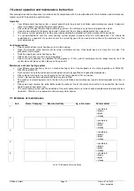
Install  the base of the frame, the cross bars and the back bars and connect the angle section according to fig. 10a.  Bases’ 
screws should be fitted with the head on the side of the angle as shown in fig. 10b.  


Define the leading edge of the mounting frame and mark the holes accordingly. 


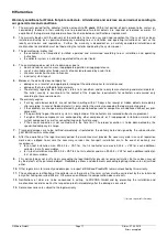
Distance of the carriers of the first mounting frame - vertical installation (I): 


1000/2000mm 

Distance of additional carriers - vertical installation  (J):  


2000 mm 


Distance of the carriers of the first mounting frame - horizontal installation (I):   


1600 mm 

Distance of additional carriers – horizontal installation  (F):   


1600 mm 


The holes of the vertical angle sections should be marked with the distance A in a right angle (use chalk line and angle). It is 
also possible to mark the holes after the assembling of the mounting frame.


Put the mounting frame on the fixing points and tighten all screws.  


The base must be connected and fixed with the surface. 
The  distance  of  the  collectors  from  the  surface  should  be  about  20  cm  to  guarantee  that  collectors  remain  free  from  snow 
during winter and that no dirt from the ground reaches the glass during strong rain.  


Fig. 10 : Base mounting


F

F

F

G

G

G

H

E

H

H

E

E

H

J

I


Fig 11 : Front view first mounting frame + extension 


Содержание Wikosun 2010

Страница 1: ...e covered if the installation instructions are followed Warranty does not cover any damages caused by non observance of this manual The correct functioning is only guaranteed if the installation instr...

Страница 2: ...Wikosun 2010 2510 Profile rails aluminum Z clamp Collector support bracket Parallel compression fitting 18mm Compression X fitting 18x18x12 x3 4 FD incl air screw and sensor pocket Insulation on site...

Страница 3: ...6 washers ST BFS BL 2 clamps for rolled steel joist 2 screws M8 2 nuts M8 ST BFS ST 2 stair bolts M10 2 ears 6 nuts 2 seals ST BFS T 2 roof hooks profiled sheeting ST BFS W 2 roof hooks corrugated sh...

Страница 4: ...s 5 mm 1 Flat section aluminum 40x5 mm l 1710 mm s 5 mm 7 Hex head screws stainless steel M8 x 20 mm 7 Hex nuts stainless steel M8 7 Lock washers M8 Chart 4 Fastening sets flat roof mounting horizont...

Страница 5: ...with reference to DIN 1055 100 DIN 1055 4 and DIN 1055 5 Determine the values of local snow loads according to country specific data Determine the values of local wind loads according to country speci...

Страница 6: ...mensionally mediated according to the number of collectors The distances between the upper and lower profile rail are as follows see fig 4 On roof mounting vertical 1500 1600 mm WIKOSUN 2010 1800 1900...

Страница 7: ...ms Smaller rafters should be doubled or trebled in width at the point where brackets are to be fixed to them see fig 6 If a foil under the roof tiles exist and is harmed during installation the openin...

Страница 8: ...al installation 0 5m 200 kg 300 kg 5 10 m 250 kg 350 kg 10 20 m 300 kg 400 kg 20 m Calculation necessary Chart 8 Loading per collector 3 3 1 1 Installation of the mounting frame on mass elements e g c...

Страница 9: ...ulated and measured For roof angles smaller than 60 the vertical angle section must be cut 25mm above the hole Install the base of the frame the cross bars and the back bars and connect the angle sect...

Страница 10: ...Position the collectors and fix them carefully The collectors are connected with each other by using the corresponding parallel compression fittings Hand tighten the bolts and protect the connecting...

Страница 11: ...shions 3 9 Hydraulic pressure test After a successful installation rinse the entire collector circulation with water Before commissioning the collector circulation must be checked with a water pressur...

Страница 12: ...450 25 18 9 540 40 22 10 5 630 40 22 12 720 50 22 13 5 810 50 28 15 900 80 Valid for parallel collector connection In the case of series connection of the same collector arrays the flow rate is halve...

Страница 13: ...ool Absorber Material Aluminium plate on copper Aluminium plate on copper Absorber coating TINOX ENERGY Alanod Mirotherm TINOX ENERGY Alanod Mirotherm Pressure loss 50 l h 49 Pa collector 54 Pa collec...

Страница 14: ...minated Switch on again your solar heating system Please never vent at sunshine or running pump Please do not undertake an additional venting process If the system s working pressure drops later on or...

Страница 15: ...no atmospheric oxygen in the system It must be ensured that the circulating pump is suitable for operation with antifreeze agents Before being filled the system should be flushed with water and the ti...

Страница 16: ...he local authority in charge Cleaning clean with liquid binding material sand kieselguhr acid binder or universal binder Recycle contaminated material separately Keep the concentrate in a cool and dry...

Страница 17: ...hidden defects immediately after emerging In case of hidden defects it is only valid for the warranty exceeding the legal warranty period if the collectors are changed or maintained by non spezialise...

Страница 18: ...ick vent valve at collectors Primary pressure exp vessel C Type Cooling function from colour unchanged brown black cloudy Flow rate m System settings Controller setting Consumer 1 e g DHW Consumer 2 e...

Страница 19: ...ollector fastening is stable User has been instructed Maintenance contract Operation of pumps checked Temperature sensores indicate realistic values Collector interior is not fogged Collector is clean...

Отзывы: