Router design
Wieland Electric GmbH | BA000868 | 08/2021 (Rev. C)
16
5.6.2
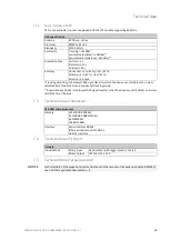
Power connector PWR
2-pin connector on front panel
Pin
Signal
Description
1
VCC (+)
Positive pole of DC supply voltage (+9 to +36 VDC)
2
GND (-)
Negative pole of DC supply voltage
Figure 8: Power connector
Power supply for router is required b9 V to +36 V DC supply. Protection against reversed po-
larity without signaling is built into the router.
The protection against reversed polarity is lost if the negative pole is grounded!
The power consumption during receiving is 2.3 W. The peak power consumption during data send-
ing is 5.5 W. For correct operation, it is necessary that the power source is able to supply a peak cur-
rent of 1.2 A.
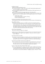
Circuit example
Figure 9: Connection of power supply
•
The positive pole VCC is marked by a red socket on the power.
•
All metal parts are connected together with the negative pole of power supply (common pole).
However, the router box may not be connected to the negative pole properly.
NOTICE
NOTICE


