


Snow Master Vario Flex 3370
7 Connecting to the Tractor
02 | 2019
3370 99 01 – 003
37
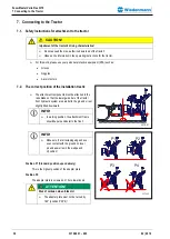
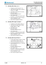
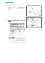
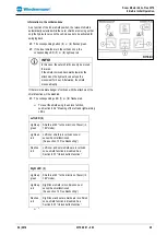
7.3.
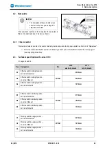
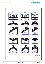
Attaching with A-frame cat. 0 A
Carefully drive up to the A-frame cat. 0. (1).
Lift the tractor front hydraulic system so that the A-
frame cat. 0 (1) engages.
Adjust safety catch (2) or insert lever screw (3).
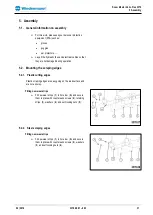
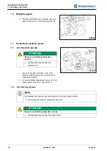
Raise parking supports.
See section 7.6 “Raising the support”.
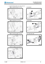
Connect hydraulic lines.
See section 7.7 „Connecting the hydraulic system“.
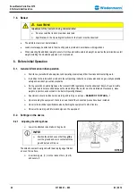
Adjust the upper guide bar so that the three-point
frame is perpendicular to the road.
Connect the power supply and control unit.
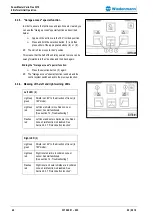
7.4.
Attaching with triangular coupling B
Carefully drive up to the triangular coupling. (1).
Lift the tractor front hydraulic system so that the
triangular coupling (1) engages.
Adjust safety catch (2)
Raise parking supports.
See section 7.6 “Raising the support”.
Connect hydraulic lines.
See section 7.7 „Connecting the hydraulic system“.
Adjust the upper guide bar so that the three-point
frame is perpendicular to the road.
Connect the power supply and control unit.
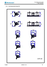
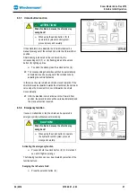
7.5.
Attaching with three-point frame C
Carefully navigate between the attachment brackets
using the tractor front hydraulic system. (A).
Insert lower guide bar and secure with bolts (1).
Peg out upper guide bar with pin (2) on three-point
frame (3) and secure.
Raise parking supports.
See section 7.6 “Raising the support”.
Connect hydraulic lines.
See section 7.7 „Connecting the hydraulic system“.
Adjust the upper guide bar so that the three-point
frame is perpendicular to the road.
Connect the power supply and control unit.


