


732W — PAGE 7
6)
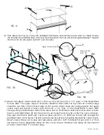
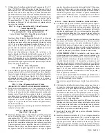
First attach the Top (L) to the Left and Right Side Panels, and then the Crown with 1¼" Black Screws
(ZI) through the predrilled holes in the top, and side panels. The top will extend approximately 1" beyond
the front of the side panels and 3/8" over the sides.
7)
FIG. 6
FIG. 7B
ZI
A
B
L
FIG. 7A
ZI
ZI
Upper Center Back
Q
L/R Back
P
Upper Center
Back
Q
Lower
Center
Back
R
Center
Shelf
C
ZM
ZM
ZM
ZM
Q
R
W
W
Z
Z
ZD
X
Y
L
Attach the Upper Center Back (Q) to the Top (L) with three #6 x 1¼" Type 17 Pan Head Black
Screws (ZM). The upper edge of the back should be flush with the top and the notched edge
should be out. Place the notched edge of the Lower Center Back (R) snugly against the upper
center back and fasten in place with three #6 x 1¼" Type 17 Pan Head Black Screws (ZM)
through the predrilled holes. Attach the lower end to the bottom shelf with three more screws.
Insert a Left/Right Back (P) into the notch in each side Panel (A & B) so that the oval cord open-
ings span the Center Shelf (CC). Fasten in place with #6 x ½" Philtruss Screws (W) through the
predrilled holes in the backs. The left and right backs will extend slightly beyond the center backs.
Attach Corner Brace (X) to base and side panels with #8 x 5/8" Pan Head Screws (ZD) 1/4" from
the bottom. Screw Adjustable Glides (Y) into corner braces. Hammer Tack Glides (Z) into bottom
of lower center back 1" from the edge.


