


732W — PAGE 9
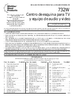
FIG. 11
11)
With the unit standing upright, attach the upper doors to the side panels with two #6 x 5/8" Flat
Head Screws (ZG) through the elongated holes. In each side panel there is a pre-punched mark
for the location of the uppermost screw in each hinge. Open and close the doors to check for
proper alignment. If adjustment is required, loosen the screws and move the doors up or down as
necessary.
12)
Level the unit by turning the adjustable glides in the corner braces. The bottom shelf has two holes
near the front for access to the adjustable glides. Insert slotted screwdriver into the slot in top of the
adjustable glide and turn clockwise to raise and counter-clockwise to lower unit. Insert Locking
Plugs (ZR) when unit is level.
IMPORTANT NOTICE:
Uneven setting of the adjustable glides can twist the unit and cause the
doors to appear out of alignment. Upon selection of the final location of the unit, rotate the
adjustable glides until the unit stands level. If the doors still appear to be out of alignment, the
elongated holes in the hinges allow for adjustment of the doors. Loosening the screws in the side
panel will allow the door to be moved up or down. The hinges on both doors may have to be
loosened to align the doors properly. Align the doors and retighten all screws.
Once you have the doors properly aligned and the unit in its final location, open the doors and
insert the third screw into the round hinge hole.
Attach the lower doors in the same way.
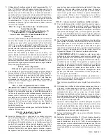
FIG. 10
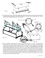
10)
Attach the backfold Hinges (ZA) to each end of the outer edge of the Upper and Lower Doors
(S&T) with #6 x 5/8" Flat Head Screws (ZG) through the elongated holes. The outer screw goes
into the predrilled hole in the door. The end of the hinge with the single fold should be attached
with its side and top flush against the door. See FIGURE 10.
The Door Skirt (ZQ) may be attached to either the left or right Upper Door. With the Upper Door
laying face down, measure in 5/8" from the outer edge and draw a light line. Lay the inner edge of
the Door Skirt (ZQ) on the line, with the bottom edge flush with the bottom of the door. Attach the
Skirt to the door with four #6 x 1/2" Philtruss Screws (W) through the predrilled holes in the skirt.
Do not insert screw in
round hole at this time.
ZA
ZG
Single
Fold
Double
Fold
FIG. 10A
ZG
ZA
S
W
W
W
W
ZQ
ZR
FIG. 12


