background image

2

SPECIFICATIONS 

ELECTRICAL RATINGS [@ 77 

O

F (25 

O

C)]:  

Input Voltage: 

120 VAC, 60 Hz (Class II transformer required)

Max. Input Current @ 24 VAC:

 800mA + MV

Relay Load Ratings:

1st Stage Gas Valve Relay:  1.5 amps @ 24 VAC, 60 Hz 
2nd Stage Gas Valve Relay: 0.5 amps @ 24 VAC, 60 Hz
Ignitor:  2.0 amps @ 132 VAC, 60 Hz
Inducer Relays:  2.2 FLA - 3.5 LRA @ 120 VAC
Humidifier Load:  1.0 A max @ 120 VAC
Electronic Air Cleaner Load:  1.0 A max @ 120 VAC

Circulator Output : 

12 mA RMS @ 30 VAC

Flame Current Requirements:
 

Minimum current to ensure flame detection:  0.3 µa DC*

OPERATING TEMPERATURE RANGE:


-40° to 175°F (-40° to 80°C)

HUMIDITY RANGE:


5% to 93% relative humidity (non-condensing)

Timing Specs:  

(@ 60 Hz**)


maximum

Flame Failure Response Time: 

2.0 sec

Gases Approved: 

Natural, Manufactured, Mixed, Liquid Pe-

troleum, and LP Gas Air Mixtures are all approved for use.

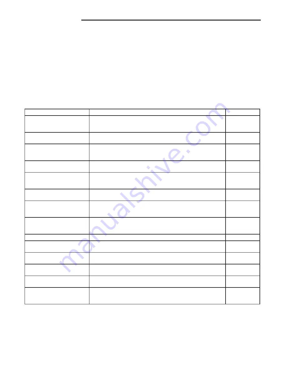
50M58-289 TIMING TABLE

(All times are in seconds, unless noted otherwise)

Event

Definition

Time

Pre-purge Time

The period of time intended to allow for the dissipation of any unburned 
gas or residual products of combustion at the beginning of a furnace 
operating cycle prior to initiating ignition

15

Igniter Warm-up Time

The length of time allowed for the igniter to heat up prior to the initiation 
of gas flow.

17

Trial for Ignition Period (TFI)

The period of time between initiation of gas flow and the action to 
shut off the gas flow in the event of failure to establish proof of the 
supervised ignition source or the supervised main burner flame.

4

Ignition Activation Period (IAP)

The period of time between energizing the main gas valve and 
deactivation of the ignition means prior to the end of TFI

3

Retries

The additional attempts within the same thermostat cycle for ignition 
when the supervised main burner flame is not proven within the first 
trial for ignition period.

2 times

Valve Sequence period

Valve sequence period equals 5 seconds trial for ignition period x 
(1 initial try + 2 retries) + 12 seconds.

15

Inter-purge

The period of time intended to allow for the dissipation of any unburned 
gas or residual products of combustion between the failed trial for 
ignition and the retry period.

30

Post-purge Time

The period of time intended to allow for the dissipation of any unburned 
gas or residual products of combustion at the end of a furnace burner 
operating cycle. Post-purge begins at the loss of flame sense.

15

Lock-Out Time

ANSI standard rated module timing.

300

Heat Delay-To-Fan-On

The period of time between proof of the supervised main burner flame 
and the activation of the blower motor at Heat speed.

30

Heat Delay-To-Fan-Off*

The period of time between the loss of a call for heat and the 
deactivation of the blower motor at Heat speed.

90/120/150/180

Cool Delay-To-Fan-On

The period of time after a thermostat demand for cool before 
energizing the circulator blower motor at Cool speed.

5

Cool Delay-To-Fan-Off

The period of time between the loss of a call for cool and the 
deactivation of the blower motor at Cool speed.

45

Automatic Reset Time

After one (1) hour of internal or external lockout, the control will 
automatically reset itself and go into an auto restart purge for 60 
seconds.

60 minutes

*These times will vary depending on option switch position.

Содержание 50M58-289

Страница 1: ...s recommended installation service instructions to ensure proper operation 50M58 289 2 Stage X 13 Style Hot Surface Ignition Control INSTALLATION INSTRUCTIONS FAILURETO READ AND FOLLOW ALL INSTRUCTIONS CAREFULLY BEFORE INSTALLING OR OPERATING THIS CONTROL COULD CAUSE PERSONAL INJURY AND OR PROPERTY DAMAGE PRECAUTIONS CONTENTS Description 1 Precautions 1 Specifications 2 Installation 3 Mounting Wir...

Страница 2: ...period of time between energizing the main gas valve and deactivation of the ignition means prior to the end of TFI 3 Retries The additional attempts within the same thermostat cycle for ignition when the supervised main burner flame is not proven within the first trial for ignition period 2 times Valve Sequence period Valve sequence period equals 5 seconds trial for ignition period x 1 initial tr...

Страница 3: ...nnections UL approved 105o C rated 16 gauge min stranded 1 16 thick insulation wire is recommended for all line voltage connections Afterinstallationorreplacement followappliancemanufacturer s recommended installation or service instructions to insure proper operation The 50M58 has only one serviceable part an automotive type fuse which protects the low voltage transformer from damage if its outpu...

Страница 4: ...D LO IND N IGN N CIRC N LINE N XFMR N HUM N EAC N R W2 W1 Y R W2 W1 Y2 CONDENSING UNITS 50M58 289 in other furnace THERMOSTAT FLAME SENSOR PROBE 2ND STAGE PRESSURE SWITCH N O HIGH LIMIT N C AUX HIGH LIMIT N C 1ST STAGE PRESSURE SWITCH N O GAS VALVE HLO HLI FP PS1 MVL MVH GND GND PS2 MV COM TR TH Low Voltage 24 VAC Line Voltage 120 VAC G G ROLLOUT SWITCH N C LEGEND N C Normally closed switch N O No...

Страница 5: ...alve FIRST STAGE W2 two stage thermostat W2 terminal or equivalent IGN 1 ignitor HOT side IGN N 5 ignitor NEUTRAL side circulator blower terminal TAP 1 L1 1 4 spade terminal input voltage 120 VAC HOT SIDE T1 XFMR 1 4 spade terminal 24 VAC transformer line voltage HOT SIDE EAC H 1 4 spade terminal air cleaner HOT side HUM 1 4 spade terminal humidifier HOT side CIRC N 1 4 spade terminal circulator b...

Страница 6: ...On 4 Off On Off On 90 sec 120 sec 150 sec 180 sec Factory default setting OPTION SWITCHES S1 1 S1 2 POSITIONS COOL CIRCULATOR SPEED 2nd Stage delay for single stage thermostats Delay Time On S1 set switch 1 2 Off Off Off 10 min On Off Auto min Off On 20 min On On Factory default setting two stage thermostat OPTION SWITCH S3 POSITION HEAT CIRCULATOR SPEED DIP Switch S3 Setting S3 1 2 1 2 1 2 1 2 Po...

Страница 7: ...emory the LED will flash two green flashes The control will flash the most re cent error first and the oldest error last last in first out There shall be 2 seconds between codes Solid LED error codes will not be displayed FAULT CODE RESET To clear the fault code memory push and hold the LAST ER ROR button for more than 5 seconds and less than 10 seconds Control will indicate this period by RAPID G...

Страница 8: ...wer failure restricted air flow through appliance or duct work Verify continuity through limit switch circuit and correct overheating cause 12 Module Ignitor contact failure Fault code indicates the module ignitor contacts are not functioning properly Replace module Solid Module internal fault condition Module contacts for gas valve not operating or processor fault Reset control if condition persi...

Отзывы: