Page 10
16940-2-0806
AVFBH-30/AVFBL-30
Do not, handle log(s) with your bare hands! Always wear gloves
to prevent skin irritation from ceramic fibers. After handling
log(s), wash your hands gently with soap and water to remove
any traces of fibers.
The positioning of the log(s) is critical to the safe and clean
operation of this heater. Sooting and other problems may
result if the log(s) are not properly and firmly positioned in the
appliance.
Refer to Figures 11 and 12 for the following warning.
Warning: Failure to position the parts in accordance with this
diagram or failure to use only parts specifically approved with
this appliance may result in property damage or personal
injury.
PROPER INSTALLATION SEQUENCE:
AVFBH-30 (Figure 11)
1. Remove casing front assembly, two (2) 10 x 1/2" screws.
2. Remove screen assembly, two (2) truss-head Phillips screws.
3. Place rear log into log support brackets. The log support
brackets are located behind main burner.
4. Place front log onto front log support.
5. Replace screen assembly with two (2) truss-head Phillips
screws from Step 2.
6. Replace casing front assembly with two (2) 10 x 1/2" screws
from Step 1.
7. Log placement is completed..
PROPER INSTALLATION SEQUENCE:
AVFBL-30 (Figure 12)
1. Remove casing front assembly, two (2) 10 x 1/2" screws.
2. Remove screen assembly, two (2) truss-head Phillips screws.
3. Place rear log into log support brackets. The log support
brackets are located behind main burner.
LOG PLACEMENT
Figure 11
Figure 12
OPTIONAL FLOOR STAND INSTALLATION
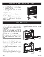
Optional VFBFS Floor Stand Installation
1. Remove (4) 10 x 1/2" screws located in bottom of heater.
2. Align clearance holes on floor stand with screw holes on
bottom of heater (See Figure 10).
3. Attach floor stand to heater with (4) 10 x 1/2" screws re-
moved in Step 1.
4. Installation of optional floor stand is completed.
Installation on Rugs and Tile
If this appliance is installed directly on carpeting, tile or other
combustible material, other than wood flooring, the appliance
shall be installed on a metal or wood panel extending the full
width and depth of the appliance.
Attention: Optional VFBFS Floor Stand meets requirement.
The base referred to above does not mean the fire-proof base as
used on wood stoves. The protection is for rugs that are extremely
thick and light colored tile.
Figure 10
4. Replace screen assembly with two (2) truss-head Phillips
screws from Step 2.
5. Replace casing front assembly with (2) 10 x 1/2" screws from
Step 1.
6. Log placement is completed.
Figure 10
Содержание AVFBH-30
Страница 15: ...Page 15 16940 2 0806 PARTS VIEW ...
Страница 19: ...Page 19 16940 2 0806 SERVICE NOTES ...


