Page 12
16940-2-0806
MAIN BURNER FLAME CHARACTERISTICS
There will be a short blue inner flame with a much larger lighter
blue secondary flame. The burner flame may have a small yel-
low tip when hot. Dust in the combustion air will produce an
orange or red flame. Do not mistake the orange or red flame for
an improper yellow flame.
On Propane gas, if a whistling noise (resonation) occurs screw
the orifice fitting toward the main burner in order to reduce the
amount of primary air. The reduction in primary air will soften
the main burner flame and will eliminate the whistling noise
(resonation).
On Propane or Natural gas, if a yellow flame occurs screw the
orifice fitting away from the main burner in order to increase the
amount of primary air. The increase in primary air will sharpen
the main burner flame and will eliminate the yellow flame.
After use, cleaning of the main burner may be required for the
proper flame. The main burner may be cleaned by forcing water
into the ports and the throat of the burner. The burner should be
blown dry or heated to remove all water before replacing. To
remove main burner, see Appliance Maintenance.
PILOT FLAME CHARACTERISTICS
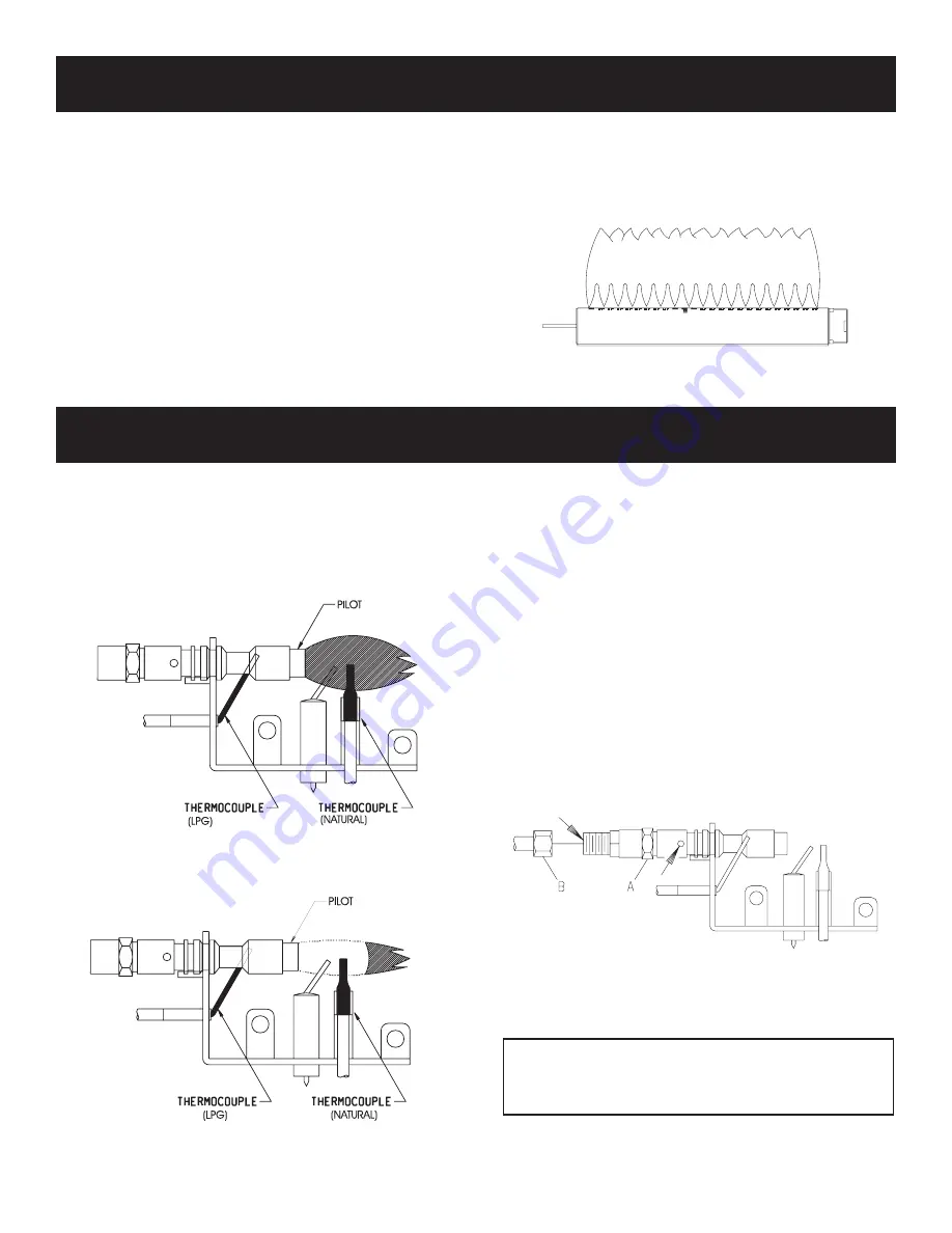
Figure 14 shows a correct pilot flame pattern. The correct flame
will be blue and will extend beyond the thermocouple. The flame
will surround the thermocouple just below the tip. A slight yellow
flame may occur where the pilot flame and main burner flame meet.
Figure 15 shows an incorrect pilot flame pattern. The incorrect
pilot flame is not touching the thermocouple. This will cause the
thermocouple to cool. When the thermocouple cools, the heater
will shut down.
Correct Flame Pattern
Figure 14
Incorrect Flame Pattern
Figure 15
If pilot flame pattern is incorrect, as shown in Figure 15
• See Troubleshooting, page 13.
Cleaning and Maintenance/Pilot
Oxygen Depletion Sensor Pilot (Figure 16)
When the pilot has a large yellow tip flame, clean the Oxygen
Depletion Sensor as follows:
1. Remove screen from casing.
2. Remove front log from front log support on AVFBH-30.
3. Remove front log support.
4. Clean the ODS pilot by loosening nut B from the pilot tubing.
When this procedure is required, grasp nut A with an open end
wrench.
5. Blow air pressure through the holes indicated by the arrows.
This will blow out foreign materials such as dust, lint and
spider webs. Tighten nut B also by grasping nut A.
6. Replace front log support.
7. Replace front log onto front log support on AVFBH-30.
8. Replace screen onto casing.
Figure 16
Figure 13
Warning:
Never use needles, wires, or similar cylindrical objects to
clean the pilot to avoid damaginh the calibrated ruby that
controls the gas flow.
Содержание AVFBH-30
Страница 15: ...Page 15 16940 2 0806 PARTS VIEW ...
Страница 19: ...Page 19 16940 2 0806 SERVICE NOTES ...


