page 3 – 14
E-Series Network / Apr 2007
X P O I N T S O F T W A R E S E T U P G U I D E
Programmable Buttons
The control surface’s programmable buttons can be used in different ways.
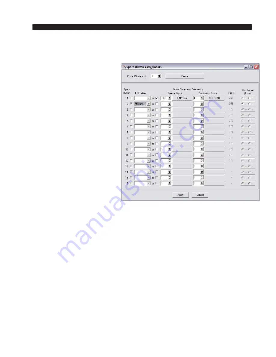
If you want a button to fire a
Salvo or make a temporary
crosspoint, select the Configure /
Spare Button LIOS menu, which will
display the form shown at the right.
To program a button to fire a Salvo,
check the box immediately to the
right of the Spare Button number,
then select a Salvo from the pulldown
list under Fire Salvo. The Salvo will
fire whenever the programmed but-
ton is pressed.
To cause the button to make a
temporary crosspoint, check the box
to the right of the word “or” on the
same line as the desired button num-
ber, then select the desired Source
and Destination Signals for the tem-
porary crosspoint. For example, let’s
say you program button 3 to tempo-
rarily connect a source named “OUT
1” to a destination named “IN 1”. As
long as you are holding button 3
down, OUT 1 will feed IN 1. If a
different signal was feeding IN 1 to
start, that connection will disappear while the button is pressed and reappear when
the button is released.
You can also control a physical logic output with a programmable button. When
the system is originally created, two signals will be auto-generated to enable
programmable button use: ExxSPAR1 is associated with buttons 1-6, and ExxSPAR2
is associated with buttons 7-12. If you look at the signal definitions of these signals,
you will find that function names are assigned to them. You can use default names,
or create your own. The key is to create a physical Logic Only destination (see page
3-20 for details), such as LOut1, and use the same function name for that destination
as you are using for programmable button that will control it. Assuming for the
moment you are working with button 1, the last step is to make a crosspoint on the
XPoint grid to connect ExxSPAR1 (remember, it deals with buttons 1-6) and your
Logic Only destination (in this case, LOut1). The combination of the crosspoint and
the matching function names causes the specified logic output port to respond to
button 1.
In a similar manner the LEDs that light up the programmable buttons can be
controlled by physical logic inputs. Once again you create a physical Logic Only
destination, map a source signal to the programmable button signal by function
name, and make the crosspoint connection in XPoint.
Note: The “xx” part of the signal name is usually the surface number in a multi surface system. These signals are located
in the horizontal Sources set of signals and are typically in the signal space above signal ID 1000 of the XPoint grid.
Содержание E-SAT
Страница 34: ...page 1 26 E Series Digital Audio Network System Flow Diagram E Series Network Jan 2008 ...
Страница 111: ...page 4 21 SAT E Mother Board MBNC 1 Load Sheet E Series Network Apr 2007 ...
Страница 112: ...page 4 22 S 16 Wheatnet E Super Hub Main Card IB 1 Load Sheet E Series Network Apr 2007 ...
Страница 114: ...page 4 24 S 8 Wheatnet E Super Hub Main Card IBA 1 Load Sheet E Series Network Jan 2008 ...
Страница 115: ...page 4 25 Micro Satellite Main Card MCS 8 MCS 8E Load Sheet E Series Network Jan 2008 ...


