background image

Pro-Guard & Uni-Guard Installation Manual 


21 


Tuning Procedures & Tips 


There are mainly two problems that affect system’s functioning and 
performance. One is that system picks up tags and labels poorly. The other is 
that system false alarms (or causes other system to do so) without tags or 
labels in detection zone. 


Low Pick up Rate 

1.  Check noise “D” (ranging from 0-

999, >400 or so is heavy noise). 

2.  Adjust MIN, GN, RE, (see diagram 

below). 

3. 

Shorten pedestal separation.


Interference with or by other
systems               

1.  Swap L & N terminals on power plug. 

2.  Adjust SYN “B” step by step. 

Please open and tune the systems one by one if there are multiple pedestals 
working together.  It will help determine which system is causing the problem. 

200

RE

Default 8

GN

MIN

Default 40 

But Tendency to 


False Alarm 

   Shorter detection range 


But lead to stability 

15

Decrease Sensitivity 

Increase Sensitivity 

Default 1 

PROBLEMS 

SOLUTIONS 

The diagram below explains how the major three tuning parameters influence 
system performance. 

MIN is the most important

Содержание Pro-Guard

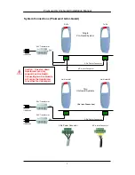
Страница 1: ...Guard TM Instruction Manual 24vac Low Voltage with 110 220vac Transformer Version 2004 April Manual Part Number WG PRG IM 042004A WG SECURITY PRODUCTS INC 3031 Tisch Way Suite 602 San Jose CA 95128 U...

Страница 2: ...ically disclaims any implied warranties of merchantability or fitness for any particular purpose Further WG Security Product Inc reserves the right to revise this publication and make changes from tim...

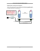
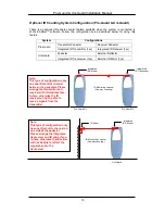
Страница 3: ...ystem Connections Pro Guard Uni Guard 7 Optional Power Connection for Pro Guard 8 Optional Split System Connection for Pro Guard two Tx s one Rx 9 Optional IR Counting System Configuration Pro Guard U...

Страница 4: ......

Страница 5: ...digital Pro Guard and Uni Guard systems are today s most technically advanced 58Khz pedestal systems on the market Both systems are fully digital software driven and have the latest DSP technology tha...

Страница 6: ...n 1 2 meters on either side 4 feet on either side Operating Temperature 0 C to 49 C 32 F to 120 F Features Benefits Self tuning electronics Software driven Network Access for remote tuning Built in al...

Страница 7: ...ection Connector WG MG ICC 7 Pedestal Power Cable Connector WG PRG PLC 8 Installation Tool WG MG IT 9 Field Indicator Pen WG MG FP 10 Interconnection Line WG MG CC 11 Instruction Manual WG PRG M 12 24...

Страница 8: ...D 5 Pedestal Power Cable Connector WG PRG PLC 6 Installation Tool WG MG IT 7 Field Indicator Pen WG MG FP 8 Instruction Manual WG PRG M 9 24vac Transformer WG PRG TR 10 IR Mirror Reflector WG UNG MIR...

Страница 9: ...ically disconnected from the branch circuit supply when replacing the fuse WARNING TO REDUCE THE RISK OF DAMAGE REPLACE ONLY WITH SAME TYPE AND RATING OF FUSE OFF ON VOLTAGE SWITCH AC POWER 24VAC OUTP...

Страница 10: ...unction Color 1 N or L Blue Brown 1 0V Blue Brown 2 Ground Green w Yellow Stripe 2 Ground Green w Yellow Stripe 3 L or N Brown Blue 3 24V Brown Blue 180 degrees phase switch Note Pin 1 and Pin 3 of th...

Страница 11: ...o Guard System Rx Tx Tx Rx 3 Pin Power Connector 6 Pin Inter Connector 24V 24V 24V Transformer 3 Pin Power Connector 110 220vac 24V Transformer 110 220vac Two Uni Guard Systems Uni Guard 1 Uni Guard 2...

Страница 12: ...enient place to connect power from one of the closer pedestals instead of connecting power directly to the transformer box 3 Pin Power Connector 6 Pin Inter Connector 24V 24V Transformer 110 220vac Si...

Страница 13: ...eiver to each transmitter This provides a convenient way for one Pro Guard receiver to slave two transmitters Please note that a second transformer box is required One transformer box can only power o...

Страница 14: ...irror 1pc Note This type of configuration only has one IR monitor channel between the pedestals Please arrange the transmitter and receiver with IR modules face to face otherwise the IR receiver will...

Страница 15: ...y with NEMA configurations International Power Supply Cord This equipment is supplied with an external power line at one end and a molded receptacle terminal block at the other end Conductors are CEE...

Страница 16: ...he three power lines 3 If the Pro Guard shuts down other manufacturers 58Khz deactivators or cause them to false alarm or other systems cause the Pro Guard to shut down or false alarm perform the foll...

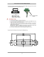
Страница 17: ...base Place cushion rings then spring rings and nuts on the spiral heads and screw the nuts to fix the base to the ground Lift the gate bottom and mount the 3 pin power line plug onto the power socket...

Страница 18: ...f the external alarm wire into each of the wire receptacle holes and release the yellow button The wire will now be held in place by the connector The external alarm switch has a rating of 1A 250vac 2...

Страница 19: ...connector on the PC Board as shown in the picture below both transmitter and receiver circled in red Pro Guard Receiver Bottom PCB Pro Guard Transmitter Bottom PCB Note If this is a Pro Guard installa...

Страница 20: ...ected from the branch circuit supply when replacing the fuse 2 Remove the fuse holder with a screwdriver rotating it in a counterclockwise direction 3 Replace the fuse in accordance with the specifica...

Страница 21: ...Pro Guard Uni Guard Installation Manual 17 Insert the gate body slick into the base track and cover the whole base Insert the two bolts through the two tunnels at the lower part of the gate body...

Страница 22: ...Pro Guard Uni Guard Installation Manual 18 Insert the nuts into the bolt shafts from the other side Use the provided tool to screw down the nuts...

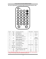
Страница 23: ...Practical range 0 200 D NSE Noise Display 2 channels 0 0 to 2 F TX OFF Turn off transmitter 1 0 to 1 E DFT Return to default settings 0 0 to 1 P PC Password change 689 see note 0 to 999 G ARM OFF Turn...

Страница 24: ...very high 1 2 of new noise or less value than several hundred increase slightly if False Alarms Adjust Gain to 0 IF Not Acceptable Check Noise Value and Sensitivity of the System C H If system is pick...

Страница 25: ...diagram below 3 Shorten pedestal separation Interference with or by other systems 1 Swap L N terminals on power plug 2 Adjust SYN B step by step Please open and tune the systems one by one if there a...

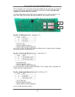
Страница 26: ...emote control then enter the password The default password if not previously changed is 689 Figure 2 Display after PSW is Pressed Input Password 689 and press CON to confirm accept the password Note I...

Страница 27: ...meter number Press CON to accept the parameter After parameter confirmation the panel will display the tag window signal If there is no tag in the detection zone the value reflects the noise level in...

Страница 28: ...eliminate crosstalk between different systems Setting the default value to b 1 will in most cases not interfere with other AM products Press SYN panel displays as per Figure 4 1 Input parameter number...

Страница 29: ...Key ID D Noise Condition Display Range 0 2 The LEDs indicate the signal level by value figures The upper value reflects the nose level from antenna channel 1 the lower value reflects the noise level f...

Страница 30: ...ow the maximum value between average noise and MIN value Key ID H Minimum signal Adjustment Suggested increment 20 practical range 0 200 Decreasing this number will increase system sensitivity but als...

Страница 31: ...rameter number Press CON to accept the parameter Input 0 will turn down the transmitting burst via software control If system power is reapplied the system will return to default state of 1 Key ID G A...

Страница 32: ...to activate the new password Note Please SAFEGUARD the new password if you have changed from the default Once the new password is activated the system will no longer recognize the 689 default passwor...

Отзывы: