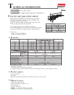
Esta herramienta eléctrica con doble aislamiento se fabrica según normas EU
73/23EWG, 89/336 CEE y 98/37/CEE. Tiene un diseño atractivo y puede ser
transportada fácilmente por sus pequeñas medidas. Proporciona una operación
segura y confiable y requiere un voltaje de 120V y una frecuencia de 60Hz. La
potencia de entrada es 600W, y las revoluciones por minuto (rpm) es de 11000.
Materiales de Metal y no metálicos pueden ser manejados con esta herramienta.
1 Datos Técnicos
2 Instalación, Instrucciones de Seguridad, Operación, Mantenimiento y
Reparación
¡ Atención!
Para protegerse contra descargas eléctricas, riesgo de lesiones y quemaduras,
medidas de seguridad básicas deben aplicarse cuando se utilizan herramientas
eléctricas!
Antes de operar esta herramienta eléctrica, lea todas las instrucciones de
funcionamiento y seguridad. Por favor siga las instrucciones para referencia
futura.
Instalación
1. Después de sacar la herramienta eléctrica del empaque, por favor compruebe si
la herramienta ha sido dañada durante el tránsito. Asegúrese de que el voltaje y la
frecuencia de la toma de corriente a utilizar coincide con los requisitos de esta
herramienta – De lo contrario, su vida corre peligro y existe la posibilidad de dañar
la herramienta. El cable tiene que ser un AWG 18x2c. Cables dañados deben ser
reemplazados por una cable del mismo tipo.
2. Revise el protector de disco. Tiene que ser colocado firmemente, el ángulo del
vértice no debe ser más de 1800 y no debe estar deforme ni dañado.
3. Disco Abrasivo
3.1 Solamente utilice discos de base reforzada con un límite con respecto a la
velocidad de pulido de no menos de 80m/s de seguridad. No debe usarse más
allá de su fecha de caducidad. No utilice discos húmedos. Desenchufe la
herramienta antes de cambiar el disco.
3.2 Utilice únicamente discos que han sido aprobadas por la MPA.
4. Si se detecta algún daño después de sacar la herramienta del empaque, tiene
que ser revisada por un electricista calificado. Desconéctelo de la fuente de
energía antes de abrir la herramienta. Piezas de repuesto pueden solicitarse según
el (cuadro 2) y la lista de piezas de repuesto.
Tipos
Peso
Dimensiones Externas (in mm):
Voltaje
Frecuencia:
Energía de Entrada:
Revoluciones por Minuto:
Eje:
Clase de aislamiento del motor:
Disco abrasivo (diámetro externo X diámetro interior x
grosor):
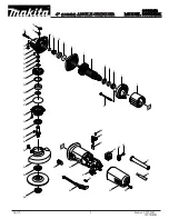
PART LIST
1
2
9
No.
No.
1
31
2
32
3
33
4
34
5
35
6
36
7
37
8
38
9
39
10
40
11
41
12
42
13
43
14
44
15
45
16
46
17
47
18
48
19
49
20
50
21
51
22
52
23
53
24
54
25
55
26
56
27
57
28
29
30
Wrench
Cord plug
Wood ruff key
Spindle
Flange
Grind wheel
Flange nut
Lock spring
Pole
Switch
Condenser
Spring
Cord jacket
Brush holder
Brush
Screw
Switch draw bar
Switch lock
Switch button
Label - A
PART DESCRIPTION
Label -B
Handle (F)
Pinio gear
Spring washer
Nut
Stator
Fan gaide
Screw
Fense - Left
Back cap
Cord clamp
Screw
Housing
Roller
Front cap
Spring washer
Screw
Shield
Screw
Fense - Right
Check ring
Bearing
C ring
Spring washer
Gearwheel
Bearing
Bearing cap
Bearing
Stop pin
Spring
Gea box
Screw
PART DESCRIPTION
Bearing shoe
Bearing
Armature
C ring
Screw
PT50360
115x22x6mm
120V
60Hz
600W
12000 rpm
5/8”
Class II
1.9kg
300x128x115
Содержание PT50360
Страница 10: ...EXPLODED VIEW 10...
Страница 11: ......


