Westell VersaLink 7550 Скачать руководство пользователя страница 70


030-300629 Rev. A 

70 

     February 2011 

User Guide 

VersaLink Wireless Gateway (Model 7550)
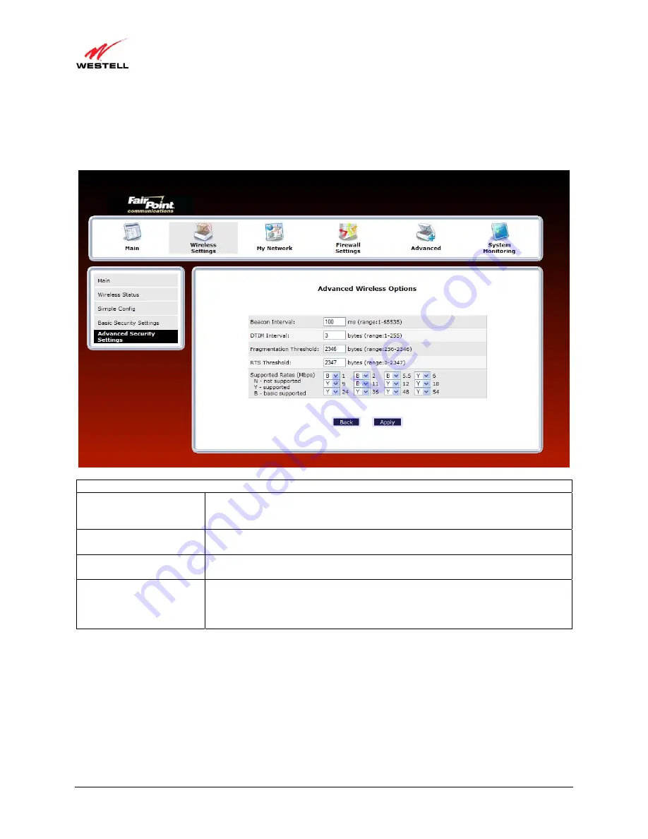
13.4.5


  Other Advanced Wireless Options 


If you select the 

Other Advanced Wireless Options

 link in the 

Advanced Security Settings

 screen, the following 

screen will appear. From the drop-down menus, select the desired settings. Then, click 

Apply

 to allow the settings to 

take effect. 


Wireless Advanced Configuration 

Beacon Interval 

The time interval between beacon frame transmissions. Beacons contain rate and 

capability information. Beacons received by stations can be used to identify the 

access points in the area. 

DTIM Interval 

The number of Beacon intervals between DTIM transmissions. Multicast and 

broadcast frames are delivered after every DTIM 

Fragmentation Threshold 

Any MSDU or MPDU larger than this value will be fragmented into an MPDU of 

the specified size. 

RTS Threshold 

RTS/CTS handshaking will be performed for any data or management MPDU 

containing a number of bytes greater than the threshold. If this value is larger than 

the MSDU size (typically set by the fragmentation threshold), no handshaking will 

be performed. A value of zero will enable handshaking for all MPDUs. 


Содержание VersaLink 7550

Страница 1: ...Copyright 2011 Westell Inc 1 February 2011 VERSALINK WIRELESS GATEWAY MODEL 7550 USER GUIDE...

Страница 2: ...saLink 14 7 INSTALLING THE USB DRIVERS 17 7 1 Installing the USB Driver for Windows 98 SE 17 7 2 Installing the USB Driver for Windows ME 23 7 3 Installing the USB Driver for Windows 2000 25 7 4 Insta...

Страница 3: ...2 Network Connections 74 15 FIREWALL SETTINGS 93 15 1 General Firewall Security Settings 93 15 2 Editing Firewall Security Rules 94 15 3 Port Forwarding 95 15 4 DMZ Host Single IP Address Passthrough...

Страница 4: ...te LAN Configuring NAT 149 16 18 Public LAN Multiple IP Address Passthrough 150 16 19 RIP Configuration 153 17 SYSTEM MONITORING 155 17 1 Gateway Status 155 17 2 Advanced Status 156 18 PORT FORWARDING...

Страница 5: ...and USB along with the following optional features E1 UPLINK Alternate WAN uplink port E4 DATA Alternate Ethernet USB connection Layer w 2 QOS with VLAN tagging HotSpot Simultaneous public private net...

Страница 6: ...ing so may result in the installed system exceeding RF exposure requirements This device must not be co located or operated in conjunction with any other antenna or radio transmitter Installers and en...

Страница 7: ...with this product It is designed to be connected to a compatible modular jack that is also compliant See installation instruction for details If this terminal equipment Model 7550 causes harm to the t...

Страница 8: ...ME NT 4 0 98 SE Macintosh OS X or Linux installed 64 MB RAM 128 MB recommended 10 MB of free hard drive space 10 100 Base T Network Interface Card NIC Internet Explorer 5 5 or later or Netscape Navig...

Страница 9: ...ing Green Wireless LAN activity is present traffic in either direction WIRELESS OFF Router power is OFF or No Link Solid Green USB link established Flashing Green USB LAN activity present traffic in e...

Страница 10: ...e Router to a telephone jack that has active ADSL service or to the DSL port of a POTS splitter E1 UPLINK Modular 8 pin RJ 45 Ethernet jack Connects the Router to a PC or Hub via 10 100 BaseT Ethernet...

Страница 11: ...upply Y cable contains o Built in 10 100 BaseT Ethernet cable labeled PC Ethernet yellow o Built in USB cable labeled PC USB blue RJ 11 Phone cable CD ROM containing User Guide in PDF format 5 6 Micro...

Страница 12: ...using additional Ethernet cables may be required Ethernet cables and DSL filters can be purchased at your local computer hardware retailer 6 VersaLink supports simultaneous 10 100 Base T Ethernet and...

Страница 13: ...hat it uplinks to another ADSL device such as an e xisting DSL or cable modem installed on your network follow the steps outlined below 1 Ensure that your existing DSL or cable modem is properly insta...

Страница 14: ...es to Your VersaLink To network computers in your home or office to VersaLink using an Ethernet installation follow the steps below 1 Ensure that you have connected your Router to your broadband servi...

Страница 15: ...a screen prompting you for the security key 4 If you are configuring the wireless station manually the Wireless card and Router must use the same security code type If you use WPA or WEP wireless sec...

Страница 16: ...Then at the other end of the Y cable plug the Ethernet jack labeled PC Ethernet yellow into the Ethernet connector marked E4 DATA on the rear panel of the Router NOTE 1 If you are networking a PC to...

Страница 17: ...e following table provides a reference to the USB driver installation instructions After you have completed the USB d river installation return to section 6 3 3 to complete the USB h ardware installat...

Страница 18: ...A 18 February 2011 User Guide VersaLink Wireless Gateway Model 7550 Figure 2 Windows 98 SE 2 Windows 98 SE Select Search for the best driver for your device Recommended See Figure 3 Click Next Figure...

Страница 19: ...iver Figure 4 Windows 98 SE Note If Fi gure 4 d oes n ot appea r at t his st ep an d Fi gure 5 ap pears wi th t he t ext USB C omposite devi ce C Windows Inf USB Inf do not continue Click Back to Step...

Страница 20: ...ows operating system CD into the CD ROM Drive Figure 7 Click OK Figure 7 Windows 98 SE 7 Windows 98 SE The system will begin copying files Figure 8 Figure 8 Windows 98 SE 8 Windows 98 SE Figure 9 may...

Страница 21: ...f the files The required files may be stored on your hard drive A common location for these files is C Windows Options Cabs Try specifying this path or the path to your CD ROM drive usually D by click...

Страница 22: ...ading the drivers Figure 11 Click Finish Figure 11 Windows 98 SE 10 Windows 98 SE Click Yes to restart your computer Figure 12 Figure 12 Windows 98 SE Congratulations You have completed the software i...

Страница 23: ...h the Router kit is in serted into the PC s CD ROM drive before beginning this installation 1 Windows ME After you connect the Router to your PC the Found New Hardware window will appear Figure 13 Aft...

Страница 24: ...reless Gateway Model 7550 2 Windows ME Windows will display the location of the driver Figure 15 Click Next Figure 15 Windows ME 3 Windows ME The window below confirms that the PC has finished loading...

Страница 25: ...on 6 3 3 Connecting USB Devices to Your VersaLink to complete the hardware installation instructions 7 3 Installing the USB Driver for Windows 2000 IMPORTANT Confirm that the CD ROM p rovided with the...

Страница 26: ...ndows 2000 The Install Hardware Device Drivers window appears Figure 20 Select Search for a suitable driver for my device recommended Click Next Figure 20 Windows 2000 3 Windows 2000 The Locate Driver...

Страница 27: ...l 7550 4 Windows 2000 The Driver Files Search Results window appears Figure 22 Note The drive letter may vary Click Next Figure 22 Windows 2000 5 Windows 2000 The window below confirms that the PC has...

Страница 28: ...SB drivers Now return to section 6 3 3 Connecting USB Devices to Your VersaLink to complete the hardware installation instructions 7 4 Installing the USB Driver for Windows XP IMPORTANT Confirm that t...

Страница 29: ...below confirms that the PC has finished loading the drivers Figure 26 Click Finish Figure 26 Windows XP Congratulations You have completed the software installation for the USB drivers Now return to...

Страница 30: ...s Vista After you connect the Router to your PC the following Found New Hardware screen will appear Figure 27 Click Next Figure 27 Windows Vista 2 Windows Vista The window below confirms that the PC h...

Страница 31: ...after you have connected VersaLink to your network To access VersaLink s Web pages your PC must be configured for DHCP Refer to your Windows help screen for information on configuring your computer f...

Страница 32: ...r further instructions IMPORTANT 1 The User Settings screen allows you to use admin as your administrator name your administrator name can match your user name However this screen does not allow you t...

Страница 33: ...ebruary 2011 User Guide VersaLink Wireless Gateway Model 7550 After you have entered the desired values click Apply If you clicked Apply the following pop up screen will appear Click OK to allow the c...

Страница 34: ...een the following screen will appear This is the main page of your Router s Web pages also referred to in this document as the home page You can access this page by clicking Main in the navigational m...

Страница 35: ...You must have active DSL service before the Router can synchronize with your ISP s equipment To determine if the Router has established a DSL link do any of the following In the My Gateway panel of th...

Страница 36: ...ng to the Internet via PPP please proceed to section 9 2 to configure your Router s broadband connection settings After you have configured the broadband settings and connected to the Internet view th...

Страница 37: ...n Internet connection with your Internet service provider Throughout this User Guide the following icons are used to indicate clicking actions that you can take with your mouse to configure the Router...

Страница 38: ...ional profiles to your Router Edit Click the Edit icon for My Connection to set up your connection profile My Connection is the name of the default connection profile that you will use to connect to y...

Страница 39: ...he Router to automatically establish a PPP session when you log on or if the PPP session goes down The Router s factory default setting is Always On If you enable the Router s timeout feature the Rout...

Страница 40: ...you want the Router to prompt you for the account password select Manual as the connection type and then click the bottom option in the Save Password field The Router will prompt you for a password on...

Страница 41: ...d will briefly display connecting this means that the Router is establishing a PPP session After Router s establishes a PPP session the PPP Status field will display Up Congratulations You can now bro...

Страница 42: ...the home page click the connected link next to Internet Status The following DSL Connection screen will appear Click disconnect to end your PPP session If you clicked disconnect the following pop up...

Страница 43: ...ed When you are ready to end your DSL session simply turn off the Router via the power switch on the Router s rear panel NOTE When you are ready to exit the Router s interface click the X close in the...

Страница 44: ...Macintosh computers must use the Router s Ethernet installation Refer to section 6 Hardware Installations for details 10 1 Opening the System Preference Screen After you have connected the Router to...

Страница 45: ...lowing screen will appear In the field labeled Name your new location change the text from Untitled to Westell Click OK 10 5 Selecting the Ethernet Configuration After clicking OK in the preceding scr...

Страница 46: ...ct System Preferences 2 In the System Preferences screen click the Network icon The Network screen will appear 3 In the Configure field in the Network screen select Built in Ethernet 4 View the IP add...

Страница 47: ...el 7550 10 7 Accessing Your Router In your Internet Explorer Web browser address bar type http 192 168 1 1 Next press Enter on your keyboard The Modem Secure screen will appear Please proceed to the M...

Страница 48: ...Whenever you change the configurable settings of your Router you must click Apply or Save where applicable to allow the changes to take effect in the Router To configure the basic settings in your Rou...

Страница 49: ...vice provider ISP click Main in the top navigational menu The following home page will appear The home page allows you to view connection information reported by your Router and to quickly access Inte...

Страница 50: ...your computer to the Internet Connection Type This field displays the protocol used for your Internet connection provided by your Internet service provider Username This field displays the username th...

Страница 51: ...der and will be available only after you have established a PPP session Internet connection with your service provider Action Zone Go to the Internet Now Click this button to go to the default page of...

Страница 52: ...eatures of your Router and guides you through the configurable settings 13 1 Wireless Status If you select Wireless Settings from the top navigational menu and then select Wireless Status in the subme...

Страница 53: ...s The stations using WPS will automatically acquire the security settings of the Router once connected For the wireless stations that do not support WPS you can connect the stations to your Router usi...

Страница 54: ...do the following 1 At the Router s Simple Config screen click the black Enable Simple Config button and then select Use Push Button Method 2 Either click the simple config button in the screen or pres...

Страница 55: ...simple config button in the screen or press the simple config button on your Router IMPORTANT You must return to the client and run the wi fi protected setup Wizard within 2 minutes of either pressin...

Страница 56: ...eway Model 7550 4 Complete the instructions in the setup Wizard and then confirm your wireless network connection to the Router Repeat these steps for each wireless client that you want to connect to...

Страница 57: ...ust be configured with VersaLink s Service Set ID SSID in order to communicate with VersaLink that is the SSID used in the wireless network adapter must be identical to VersaLink s SSID The default SS...

Страница 58: ...cess to your computer WEP Key Entry Type Factory Default Hex Choose the desired WEP Key Entry Type from the drop down menu A WEP key is treated as either a string of text ASCII characters or a set of...

Страница 59: ...256 bit WEP encryption If WEP is selected any station can connect to the Router as long as its SSID matches the Router s SSID WPA Selecting WPA allows you to enable a pre shared key for home network o...

Страница 60: ...13 4 1 Securing the Wireless Traffic In the Advanced Security Settings screen select one of the following options to secure your wireless traffic WEP Clicking this option allows you to enable a WEP ke...

Страница 61: ...will be displayed NOTE A WEP key is treated as either a string of text ASCII characters or a set of hexadecimal Hex characters The number of text characters must be either 5 for 64 40 bit encryption 1...

Страница 62: ...up screen to continue The following screen appears Enter the appropriate values in the fields and then click Apply to allow the settings to take effect NOTE A WPA key is treated as either a string of...

Страница 63: ...that support WPA WPA2 or WPA Any to connect to the Router WPA Allows stations that support WPA v 1 to connect to the Router WPA2 Allows stations that support WPA v 2 to connect to the Router WPA2 Pre...

Страница 64: ...SSID Broadcast is enabled any computer or wireless device using the SSID of ANY can see the Router To prevent this from happening click the Disable option This will disable SSID Broadcast so that onl...

Страница 65: ...er By enabling the Access List you can permit or restrict wireless access to the Router based on specific MAC addresses To limit access to the Router using the MAC address of specific wireless devices...

Страница 66: ...h are set to Allowed will have access to the Router Blocked This allows a computer to remain in the table but it is not allowed access to the Router MAC Address The MAC address assigned to the compute...

Страница 67: ...entered into the fields After you have entered your values and clicked Apply in the preceding screen the following pop up screen will appear The pop up screen indicates that wireless access may be int...

Страница 68: ...licked OK in the pop up screen the following screen will appear The MAC address has been added to the list of MAC addresses Confirm that a ckeck mark is displayed Enable Access List check box and then...

Страница 69: ...er based on technology type From the drop down menu select the desired setting Then click Apply to allow the settings to take effect 11b only Communication with VersaLink is limited to 802 11b 11g onl...

Страница 70: ...e and capability information Beacons received by stations can be used to identify the access points in the area DTIM Interval The number of Beacon intervals between DTIM transmissions Multicast and br...

Страница 71: ...connection used to interface with your Router IP Address The IP address assigned to your computer IP Address Source The method by which your computer receives its IP address MAC Address The Media Acce...

Страница 72: ...k Close to return to the My Network page 14 1 2 Rename Device In the My Network panel click the Rename Device link to rename a device on your network In the following screen type the desired name in t...

Страница 73: ...rom your network or click Clear All to remove all devices from your network 14 1 4 Enable Application In the My Network panel click the Enable Application link to set up applications for your service...

Страница 74: ...roadband connection settings in the Network Connections screen click the Broadband Connection DSL link The Basic DSL Configuration screen will appear Refer to section 14 2 1 for details about this fea...

Страница 75: ...efined by data The VPI VCI and account parameters are provided by your Internet service provider IMPORTANT You should not change the VPI VCI settings unless instructed by your Internet service provide...

Страница 76: ...Editing VC Protocol Settings The following sections discuss your virtual connection VC settings A virtual connection VC identifies a connection through the service provider s ATM network to your ISP...

Страница 77: ...d box contains a check mark When this setting is enabled the Router will allow Broadcast IP packets to from the WAN When this setting is disabled box is cleared the Router will block Broadcast IP pack...

Страница 78: ...the VCs list click the collapse icon NOTE 1 A VC s Status field must display Enabled before you can edit its VC settings 2 The actual values displayed in the following screen may vary depending on the...

Страница 79: ...This field allows you to change your VPI Virtual Path Indicator value for a particular VC which is defined by yours provider VCI This field allows you to change your VCI Virtual Channel Indicator val...

Страница 80: ...at your Internet service provider s request LCP Echo Disable Factory Default Disabled If checked this option will disable the modem LCP Echo transmissions LCP Echo Failures Indicates number of contin...

Страница 81: ...Router s Protocol Settings for PPPoE or PPPoA To configure the Router s protocol settings for PPPoE or PPPoA access to the VC 1 Configuration screen as explained earlier in section 14 2 2 1 Editing V...

Страница 82: ...as the selected Protocol The PPPoA and PPPoE screens have identical configuration options with the exception of the Tunneling feature Tunneling is available only for PPPoE protocol and is not display...

Страница 83: ...Editing VC Protocol Settings To configure the Router s Bridge settings follow these steps at the VC 1 Configuration screen 1 Select Bridge in the Protocol drop down menu 2 Select the desired Bridge m...

Страница 84: ...n IP address from a DHCP server in the network or the IP address can be assigned t o the client PC statically Bridge Routed Bridge Routed B ridged E ncapsulation RBE i s t he process by which a bridg...

Страница 85: ...m rate at which cells can be transmitted across a virtual circuit specified in cells per second and defined by the interval between the transmission of the last bit of one cell and the first bit of th...

Страница 86: ...the known RFC1483 bridging issues including broadcast storms and security The modem will g et a WAN IP address through DHCP or can b e assig ned statically NAT will use th e g lobal address assigned t...

Страница 87: ...t Allows you to either Enable or Disable the DHCP Client Select enable DHCP Client to obtain IP address automatically Select disable DHCP Client to use the static IP address that you enter into fields...

Страница 88: ...ecting th is option allo ws y ou t o use VersaLink as an Et hernet Gateway for example connecting to a DSL or cable m odem or to another ADSL device that provides WAN access In WAN Uplink mode the Rou...

Страница 89: ...the rear of the Router is enabled and is the WAN uplink to another ADSL device through which you will make your Internet connection Remember you must click Apply to allow the settings to take effect...

Страница 90: ...o another ADSL device through which you will make your Internet connection Remember you must click Apply to allow the settings to take effect in the Router NOTE 1 When using the optional E1 UPLINK por...

Страница 91: ...Router Or follow the instructions in section 16 2 Restore Defaults to restore the Router to factory default settings The actual information displayed in this screen may vary depending on network conn...

Страница 92: ...n the host computer to connect to the Internet Service Provider by bypassing the Router s capability to do this DHCP Client Selecting a option allows you to either Enable or Disable the DHCP Client Cl...

Страница 93: ...low the instructions in section 16 2 Restore Defaults to restore the Router to factory default settings The factory default security level for your Router is No Security None General Firewall Settings...

Страница 94: ...you do not change the settings in this screen If you need to reset your Router to factory default settings push the reset button on the rear of the Router Or follow the instructions in section 16 2 Re...

Страница 95: ...vice s performance and configuration Do you want to proceed Click Yes to proceed If you clicked Yes in the preceding warning screen the following Port Forwarding screen will be displayed This feature...

Отзывы: