background image

36

S

HELF

/H

ANGER

A

SSEMBLY

C

ONTINUED

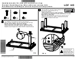
To install a Shelf, do as follows.
1. Align one of the Shelf Supports (7) to the 

3

/

8

" diameter clearance holes on the inside surface 

of the Left Hand Back Panel next to the Right Hand Side Panel as shown below. 

Orient the Tabs to face away from the Back Panel.

2. Using the Hex Insert Bit, fasten the Support Bar with four Hex Socket Button Head Screws (4).

The screws fasten to a screw insert.

3. Repeat steps 1 and 2 for the remaining Shelf Support (7). Make sure that the Shelf Support

Tabs are oriented as shown below.

Left Hand Back Panel

3

/

8

" Clearance Hole

Right Hand Back Panel

Shelf Support Tab 

facing away

from the Right Hand Back

Panel

Shelf Support Tab 

facing

toward

the Right Hand

Back Panel

3

/

8

" Clearance Hole

Shelf Support Tab

Hex Socket Button Head

Screw, 

5

/

8

" (4)

Shelf Support (7)

Shelf Support (7)

Shelf Support (7)

Hex Socket Button Head

Screw, 

5

/

8

" (4)

F

IXED

S

HELF

A

SSEMBLY

Содержание Corner Cabinet

Страница 1: ...location Refer to the illustrations on the following pages If you need additional information contact Wenger Corporation using the information below Wenger Corporation 2014 Printed in USA 08 14 Part 250A893 05 Wenger Corporation 555 Park Drive P O Box 448 Owatonna Minnesota 55060 0448 Questions Call USA 1 800 4WENGER 493 6437 Worldwide 1 507 455 4100 www wengercorp com CONTENTS Safety 2 Important ...

Страница 2: ...assembling or installing Wenger Corporation products If any questions or problems arise call Wenger Corporation at 1 800 887 7145 MANUFACTURER The Corner Cabinet is manufactured by Wenger Corporation 555 Park Drive Owatonna MN 55060 1 507 455 4100 1 800 733 0393 www wengercorp com WARRANTY This product is guaranteed free of defects in materials and workmanship for ten full years from date of shipm...

Страница 3: ...Corner Cabinet Parts List 4 Corner Cabinet Fasteners Parts List 4 Corner Cabinet Assembly 5 Level the Cabinet 21 Assemble Cabinet Connector Bracket 22 Door Assembly Fasteners Parts List 23 Door Assembly Parts List 23 Door Assembly Required Tools 23 Door Assembly 24 Wood Door Assembly 25 Grille Door Assembly 31 ...

Страница 4: ...2 X001962 3 Tack Glide X001757 14 Bracket Connector Cabinet 145A288 4 Wood Dowel X002540 15 Side Panel RH Corner Cabinet 250A145 _ 5 Leveler Glide 3 8 16 x 21 2 X002561 16 Side Panel LH Corner Cabinet 250A144 _ 6 Hex Socket Machine Screw 1 57 40mm 145L193 17 Back Panel RH Corner Cabinet 250A294 _ 7 Hex Socket Lag Screw 145R472 18 Back Panel LH Corner Cabinet 250A293 _ 8 Screw Insert 8 32x7 16 250A...

Страница 5: ...the right 3 Inventory the hardware package and make sure that all required hardware is present Discard any items not used during the assembly Item Description 15 Right Hand Side Panel 16 Left Hand Side Panel 17 Right Hand Back Panel 18 Left Hand Back Panel 19 Top Panel 20 Bottom Frame 21 Upper Frame 22 Filler Strips one long one short 23 Deflector Panel Use only with Revolving Options CORNER CABIN...

Страница 6: ... Inserts 9 into the clearance holes on the outside surface of the Top Panel 19 NOTE Numerical notations that follow part names in this document refer to part list item numbers on pages 4 and 5 Top Panel 19 Screw Insert 1 4 20 x 5 8 9 Clearance Hole Screw Insert 1 4 20 x 5 8 9 Install these only with Revolving Shelf Option Outside Surface CORNER CABINET ASSEMBLY CONTINUED NOTE Depending on Corner C...

Страница 7: ...e holes in the Left Hand Back Panel 18 as shown below Shelf Hanger Bar option only 9 Using the mallet drive three Wood Dowels 4 into the three pilot holes on the top edge of the Panel 10 Using the mallet drive two Tack Glides 3 into the bottom surface of the Left Hand Back Panel 18 as shown below Each Tack Glide 3 should be about 11 2 from the corner NOTE Depending on Corner Cabinet configuration ...

Страница 8: ... Dowels 4 into the three 5 16 diameter pilot holes on the top edge of the Panel Refer to the illustration below 14 Using the mallet drive two Tack Glides 3 into the bottom surface of the Right Hand Back Panel 17 about 11 2 from each bottom corner as shown below Right Hand Back Panel 17 3 8 Pilot Hole Bottom Edge of Panel Left Hand Edge of Panel Outside Surface Wood Dowel 4 5 16 Pilot Hole 3 16 Pil...

Страница 9: ...les in the left Right Hand Side Panel 15 as shown below Shelf Hanger Bar option shown 17 Using a mallet drive the Screw Inserts 8 into the 1 4 clearance holes in the Right Hand Side Panel 15 as shown below Shelf Hanger Bar option shown NOTE Depending on Corner Cabinet configuration hole positioning in the individual panels may vary Screw Insert 8 32 x 7 16 8 Screw Insert 1 4 20 x 5 8 9 Right Hand ...

Страница 10: ...nel 20 Using the mallet drive two Tack Glides 3 into the bottom surface of the Right Hand Side Panel 15 about 11 2 from each bottom corner as shown below NOTE Depending on Corner Cabinet configuration hole positioning in the individual panels may vary Right Hand Side Panel 15 with inside surface facing up Wood Dowel 4 Top Edge Top Edge Wood Dowel 4 5 16 Clearance Hole 7 16 Deep 3 16 Pilot Hole thr...

Страница 11: ...t Hand Side Panel 16 as shown below 23 Using a mallet drive twelve Screw Inserts 8 into the 1 4 clearance holes in the Left Hand Side Panel 16 as shown below NOTE Depending on Corner Cabinet configuration hole positioning in the individual panels may vary Screw Insert 1 4 20 x 5 8 9 3 8 Clearance Hole Left Hand Side Panel 16 Top Edge of Panel Left Hand Edge of Panel Bottom Edge of Panel Outside Su...

Страница 12: ...ide Panel 26 Using the mallet drive two Tack Glides 3 into the bottom surface of the Left Hand Side Panel 16 about 11 2 from each bottom corner as shown below NOTE Depending on Corner Cabinet configuration hole positioning in the individual panels may vary Left Hand Side Panel 16 with inside surface facing up Wood Dowel 4 Top Edge Top Edge Wood Dowel 4 5 16 Pilot Hole 7 16 Deep 3 16 Clearance Thro...

Страница 13: ...r with five Hex Lag Screws 7 Pilot holes locate the position of the Hex Lag Screws Right Hand Back Panel 17 Left Hand Back Panel 18 Hex Lag Screw 7 Pilot Holes Right Hand Back Panel 17 Left Hand Back Panel 18 Hex Lag Screw 7 Pilot Hole Clearance Hole Clearance Hole CORNER CABINET ASSEMBLY CONTINUED NOTE Depending on Corner Cabinet configuration hole positioning in the individual panels may vary ...

Страница 14: ...to the Right Hand Back Panel 17 with five Hex Lag Screws 7 Pilot holes locate the position of the Hex Lag Screws NOTE Do not tighten the Lag Screws Allow the head of each Lag Screw to extend 1 2 from the surface of the Side Panel Right Hand Back Panel 17 Right Hand Side Panel 15 Hex Lag Screw 7 Pilot Hole Right Hand Back Panel 17 Right Hand Side Panel 15 Hex Lag Screw 7 Clearance Hole CORNER CABIN...

Страница 15: ...Panel 16 to the Left Hand Back Panel 18 with five Hex Lag Screws 10 Pilot holes locate the position of the Hex Lag Screws NOTE Do not tighten the Lag Screws Allow the head of each Lag Screw to extend 1 2 from the surface of the Side Panel Hex Lag Screw 7 Left Hand Side Panel 16 Hex Lag Screw 7 Pilot Hole Left Hand Back Panel 18 Clearance Hole Right Hand Back Panel 17 CORNER CABINET ASSEMBLY CONTIN...

Страница 16: ... Lag Screws 7 that fasten the Side Panels to the Back Panels 36 Using the Hex Insert Bit 13 fasten a Six Hex Lag Screws 7 through the clearance holes in the Top Panel 19 into the two Back Panels b Three Hex Lag Screws 7 through the clearance holes in the Left Hand Side Panel 16 into the pilot holes in the Top Panel c Three Hex Lag Screws 7 through the clearance holes in the Right Hand Side Panel 1...

Страница 17: ...the Right Hand Side Panel 15 using a Pan Head Screw 11 4 long 11 for each Trim Strip as shown in the illustration below Pan Head Screw painted 11 4 long 11 Trim Strip 12 Trim Strip 12 Right Hand Side Panel 15 Left Hand Side Panel 16 CORNER CABINET ASSEMBLY CONTINUED ...

Страница 18: ...Upper Frame to the Left Hand Side Panel 16 with two Hex Socket Machine Screws 10 d Using the Hex Insert Bit 13 fasten the Upper Frame to the Right Hand Side Panel 17 with two Hex Socket Machine Screws 10 Top Panel 19 Left Hand Side Panel 16 Right Hand Side Panel 17 Upper Frame 21 Hex Socket Machine Screw 1 77 45 mm long 10 Hex Socket Machine Screw 1 77 45 mm long 10 The Top Panel Right Hand Side P...

Страница 19: ...surface of the Bottom Frame 20 as shown in the illustration below 40 Using the mallet drive a Tube Plug 2 into each open end of the Bottom Frame 20 Bottom Frame 20 Leveler Glide 3 8 16 x 21 2 5 Leveler Glide 3 8 16 x 21 2 5 Bottom Frame 20 Leveler Glide 3 8 16 x 21 2 5 Leveler Glide 3 8 16 x 21 2 5 Bottom Frame 20 Weld Nut Tube Plug 2 Tube Plug 2 The Weld Nut must be on the bottom of the Bottom Fr...

Страница 20: ...t 13 fasten the Bottom Frame to the Left Hand Side Panel 16 with two Hex Socket Machine Screws 10 d Using the Hex Insert Bit 13 fasten the Bottom Frame to the Right Hand Side Panel 15 with two Hex Socket Machine Screws 10 Left Hand Side Panel 16 Right Hand Side Panel 15 Hex Socket Machine Screw 1 77 45 mm long 10 The Right Hand Side Panel and Left Hand Side Panels are shown disassembled for clarit...

Страница 21: ...2 Adjustments to 3 and 4 may be necessary 4 Adjust Leveler Glides at points 1 and 2 adjustments to 5 may be necessary until the edges Z and W of the cabinet are plumb front to back 5 Re measure A and B with a measuring tape and make sure that A is still equal to B 1 32 Readjust if necessary steps 2 to 4 A B 1 2 3 4 5 X Z Y W CAUTION DO NOT try to level the cabinet to match soffits CAUTION DO NOT t...

Страница 22: ...or Bracket 19 to the Corner Cabinet Top Panel using four 1 Pan Head Screws 5 8 long 5 Connect the Bracket to the wall with the appropriate fasteners NOTE Numerical notations that follow part names in this document refer to part list item numbers on pages 22 and 23 CAUTION The Corner Cabinet can be unsafe unless it is fastened to a wall as described in this procedure Use a method to fasten the brac...

Страница 23: ...ert Bit 5 32 X001962 7 Flat Head Screw painted 250A507 _ 16 Door Full 27 Wood 250A332 _ 8 Hex Cap Insert Nut 250A510 _ Door Full 27 Grille 250A302 _ 9 Door Stop Cabinet 145L098 19 Cabinet Connector Bracket 145A288 DOOR ASSEMBLY PARTS LIST DOOR ASSEMBLY REQUIRED TOOLS Variable Speed Drill 6 foot Ladder Mallet Philips Screwdriver Hex Insert Bit Pan Head Screw 5 8 1 Screw Insert 8 32 x 7 16 oyster 6 ...

Страница 24: ...ackage and make sure that everything required is present Discard any items not used during the assembly IMPORTANT The following Door Assembly procedures are for a left side hinge For a right side hinge the images would be mirrored NOTE Make sure that the cabinet is level before assembling the door Item Description 9 Door Stop Cabinet 10 Handle Wood Full Door 11 Latch Assembly Full Wood Door 12 Hin...

Страница 25: ... Inserts 6 into the eight clearance holes in the Door as shown below NOTE Reference Holes do not go through are between the hinge clearance holes on the inside surface Refer to the illustration at the bottom of this page Wood Door 16 Screw Insert 8 32 x 7 16 6 Outside Surface Clearance Hole Wood Door 16 Clearance Hole Bottom Edge Reference Hole Inside Surface Pilot Hole DOOR ASSEMBLY CONTINUED ...

Страница 26: ...r Wood Door Hinges 12 to the clearance holes in the Wood Door and using a phillips head screwdriver fasten the HInges to the Screw Inserts in the Door using eight Flat Head Screws 5 matches hinge color c Fasten one Flat Head Screw 7 Matches hinge color to each Hinge using a phillips head screwdriver Wood Door 16 Inside Surface Flat Head Screw 3 4 long 5 Flat Head Screw 5 8 long 7 Wood Door Hinge 1...

Страница 27: ...g a Hex Insert Bit 15 c Insert the two Wood Door Handle Threaded Post 10 into the two clearance holes as shown below d Insert two Hex Cap Insert Nuts 8 into the two clearance holes and tighten the Nuts to the Wood Door Handle Threaded Posts using a Hex Insert Bit 15 NOTE All door hardware should match hinge color Hex Cap Insert Nut 8 Wood Door 16 Wood Door Handle 10 Wood Door Latch Assembly 11 Cle...

Страница 28: ... Screws 1 through the clearance holes in the Catch and into the two Pilot Holes in the inside surface of the Top Panel Use a phillips head screw driver to tighten the Screws See the illustration below Door Catch 13 Pan Head Screw 5 8 long 1 Top Panel DOOR ASSEMBLY CONTINUED WOOD DOOR ASSEMBLY CONTINUED ...

Страница 29: ...wide lip facing the Corner Cabinet Door Stop and the narrow lip facing away from the Corner Cabinet Door Stop b Attach the Door Stop Assembly to the inside surface of the Right Hand Side Panel with two Painted Pan Head Screws 4 using a phillips head screwdriver Right Hand Side Panel Hex Nut with Lock Washer 2 Corner Cabinet Door Stop 14 Cabinet Door Stop 9 Truss Head Screw 3 4 long 3 Pan Head Scre...

Страница 30: ...Flat Head Screws 5 as shown below A screw may be inserted into the rear most hole of the cabinet and the door may be hung from it by placing the slotted hole in the hinge onto the screw and moving the hinge forward until the other two screw inserts are exposed Tighten the three screws in each hinge c Attach the lower hinges in the same manner NOTE All door hardware should match hinge color Wood Do...

Страница 31: ...the Corner Cabinet Door Stop and the wide lip facing away from the Corner Cabinet Door Stop b Attach the Door Stop Assembly to the inside surface of the Right Hand Side Panel with two Painted Pan Head Screws 4 using a phillips head screwdriver Right Hand Side Panel Hex Nut with Lock washer 2 Corner Cabinet Door Stop 14 Cabinet Door Stop 9 Truss Head Screw 3 4 long 3 Pan Head Screw 3 4 long 4 Right...

Страница 32: ... by using three Painted Flat Head Screws 5 as shown below A screw may be inserted into the rear most hole of the cabinet and the door may be hung from it by placing the slotted hole in the hinge onto the screw and moving the hinge forward until the other two screw inserts are exposed Tighten the three screws in each hinge c Attach the lower hinges in the same manner Grille Door 16 Top Panel Right ...

Страница 33: ...nger Bars CONTENTS Important User Information 34 Shelf Hanger Bar Required Tools 34 Shelf Hanger Bar Parts List 34 Shelf Hanger Bar Fasteners Parts List 34 Shelf Hanger Bar Assembly 35 Brass Clothes Hook Assembly 35 Fixed Shelf Assembly 36 Band Uniform Hanger Bar Assembly 38 Choral Robe Hanger Assembly 39 ...

Страница 34: ...er Cabinet Shelf Hanger Bar must comply with the Warnings and Cautions in the Safety Section INTENDED USE The Wenger Corner Cabinet Shelf Hanger Bar is intended for indoor use in normal ambient temperature and humidity conditions it must not be exposed to prolonged outside weather conditions The Wenger Corner Cabinet Shelf Hanger Bar is intended to be permanently installed only as described in thi...

Страница 35: ...ok Screws 6 Shelf 7 Shelf Support 8 Hanger Bar 35 1 Install four Brass Clothes Hooks 5 as follows a Fasten each Brass Clothes Hook 5 to the inside surface of the Left Hand Side Panel with two Brass Clothes Hook Screws b Pilot holes 1 8 diameter on the inside surface of the Left Hand Side Panel locate the Clothes Hooks SHELF HANGER BAR ASSEMBLY BRASS CLOTHES HOOK ASSEMBLY Left Hand Back Panel Left ...

Страница 36: ... Hex Socket Button Head Screws 4 The screws fasten to a screw insert 3 Repeat steps 1 and 2 for the remaining Shelf Support 7 Make sure that the Shelf Support Tabs are oriented as shown below Left Hand Back Panel 3 8 Clearance Hole Right Hand Back Panel Shelf Support Tab facing away from the Right Hand Back Panel Shelf Support Tab facing toward the Right Hand Back Panel 3 8 Clearance Hole Shelf Su...

Страница 37: ...lf Support with the pilot holes on the rear bottom side of the Shelf and attach with two Pan Head Screws 3 Clearance Hole Pan Head Screw 13 4 3 Front Shelf Support 7 Pilot holes on bottom of Shelf Rear Shelf Support 7 5 To install a bottom Shelf 6 do as follows a Apply five Velcro Strips 9 to the front and rear Shelf Supports 7 as shown below b Remove the paper backing from the five Velcro Strips ...

Страница 38: ...screwdriver fasten the Hanger Bar to the Left Hand Back Panel and the Right Hand Side Panel with four Truss Head Screws 1 The screws fasten to a screw insert 3 Repeat steps 1 and 2 for the second Hanger Bar 8 using the lowest set of 1 4 diameter clearance holes these are about 38 below the upper set of holes as shown below 1 4 Clearance Holes Truss Head Screw 3 4 1 Hanger Bar 8 Right Hand Side Pan...

Страница 39: ...gn the clearance holes in the end of a Hanger Bar 8 to the mid pair of 1 4 diameter clearance holes 13 below the upper set of holes in the Left Hand Back Panel and the Right Hand Side Panel 2 Using a phillips head screwdriver fasten the Hanger Bar to the Left Hand Back Panel and the Right Hand Side Panel with four Truss Head Screws 1 The screws fasten to a screw insert 3 Discard the second Hanger ...

Страница 40: ...40 This page is intentionally blank ...

Страница 41: ...e Assemblies and two Half Shelf Assemblies CONTENTS Important User Information 42 Revolving Shelf Required Tools 42 Revolving Shelf Parts List 42 Revolving Shelf Fasteners Parts List 42 Revolving Shelf Assembly 42 Assemble Deflector Panel to the Corner Panel 44 Assemble Base Frame and Center Column 45 Assemble a Half Shelf to the Center Column 48 Assemble a Flag Choral Robe Pack 49 ...

Страница 42: ...et Revolving Shelf must comply with the Warnings and Cautions in the Safety Section INTENDED USE The Wenger Corner Cabinet Revolving Shelf is intended for indoor use in normal ambient temperature and humidity conditions it must not be exposed to prolonged outside weather conditions The Wenger Corner Cabinet Revolving Shelf is intended to be permanently installed only as described in this manual RE...

Страница 43: ... below Make sure that all parts are present Item numbers refer to the Part List on page 42 and the table below 3 Inventory the hardware package and make sure that all required hardware is present Discard any items not used during the assembly Item Description 8 Deflector Panel 9 Top Plate Assembly 10 Base Frame Assembly 11 Center Column Assembly 12 Half Shelf Assembly 13 Flag Choral Robe Assembly ...

Страница 44: ...screw it into the upper Pilot Hole in the Left Hand Back Panel 4 Repeat step 3 fastening a Truss Head Screw 7 to the upper right Pilot Hole on the Right Hand Back Panel 5 Continue attaching the Deflector Panel with the other 12 Truss Head Screws NOTE Numerical notations that follow part names in this document refer to part list item numbers on pages 42 and 43 Truss Head Screw 5 8 long 7 Right Hand...

Страница 45: ...s into the Base Frame until the head of each Leveler Glide is nearly against the lower surface as shown below Threaded Hole 3 8 16 Leveler Glide 3 long 14 Threaded Hole 3 8 16 Leveler Glide 3 long 14 Bass Frame Assembly 10 Turn the Leveler Glide 14 into the threaded hole until it is nearly flush with the lower surface of the Base Frame Assembly 10 Lower Surface Upper Surface Head REVOLVING SHELF A...

Страница 46: ...6 NOTE One person should hold the Center Column Assembly 11 in an upright position until completing step 3 on the next page d Insert the the Top Plate Assembly Post 9 into the Clearance Hole at the top of the Center Column Assembly Top Plate Assembly 9 Bass Frame Assembly 10 Thrust Washer 6 Center Column Assembly 11 Bass Frame Assembly Post Top Plate Assembly Post facing downward Center Column Ass...

Страница 47: ...nsert four Capscrews 3 into the clearance holes on the Base Frame Assembly 10 and using a 9 16 wrench or socket and ratchet screw the Capscrews 3 into the Bottom Frame e Turn the Top Plate Assembly 9 so that the four Clearance Holes in the corners align with the four holes on the inside surface of the Top Panel these holes have Screw Inserts on the outside surface f Insert four Capscrews 1 into th...

Страница 48: ...d of the Capscrew 4 and push the Shelf against the Center Column 4 Place a Flat Washer 2 onto the threaded end of the Capscrew 4 5 Screw a Locknut 5 onto the Capscrew 4 6 Repeat steps 2 4 and 5 at the lower clearance hole 7 Using two 9 16 wrenches or sockets and ratchets tighten the Capscrews and Locknuts 8 Install additional Half Shelf Assemblies by repeating steps 1 to 7 Half Shelf Assembly 12 C...

Страница 49: ...rance Hole in the Flag Choral Robe Assembly until the threaded end extends from the the Center Column Assembly c Align the Upper Clearance Hole in a second Flag Choral Robe Assembly 13 to the threaded end of the Capscrew 4 and push the Shelf against the Center Column d Place a Flat Washer 2 onto the Capscrew 4 e Screw a Locknut 5 onto the Capscrew 4 f Repeat steps b to e using the third clearance ...

Страница 50: ...the top Clearance Hole in the fourth Flag Choral Robe Assembly 13 to the Capscrew 4 and push the Flag Choral Robe Assembly 13 against the Center Column d Place a Flat Washer 2 onto the Capscrew 4 e Screw a Locknut 5 onto the Capscrew 4 f Repeat steps b to e using the lowest clearance hole shown in the illustration below g Using two 9 16 wrenches or sockets and ratchets tighten the Capscrews and Lo...

Страница 51: ...g Choral Robe Packs locate the Flag Choral Robe Assemblies 13 about at the top and at the mid point on the Center Column Assembly and the Half Shelf Assemblies 12 at the bottom as shown below Place a Pad on the upper surface of each Half Shelf Assembly 12 Pad Flag Choral Robe Assembly 13 approximately at the top Center Column Assembly 11 Half Shelf Assemblies 12 Revolving Garment Option Place the ...

Страница 52: ...52 This page is intentionally blank ...

Отзывы: