Wegner Crane CFW500 series Скачать руководство пользователя страница 61


Parameters Description 


Crane | 61 


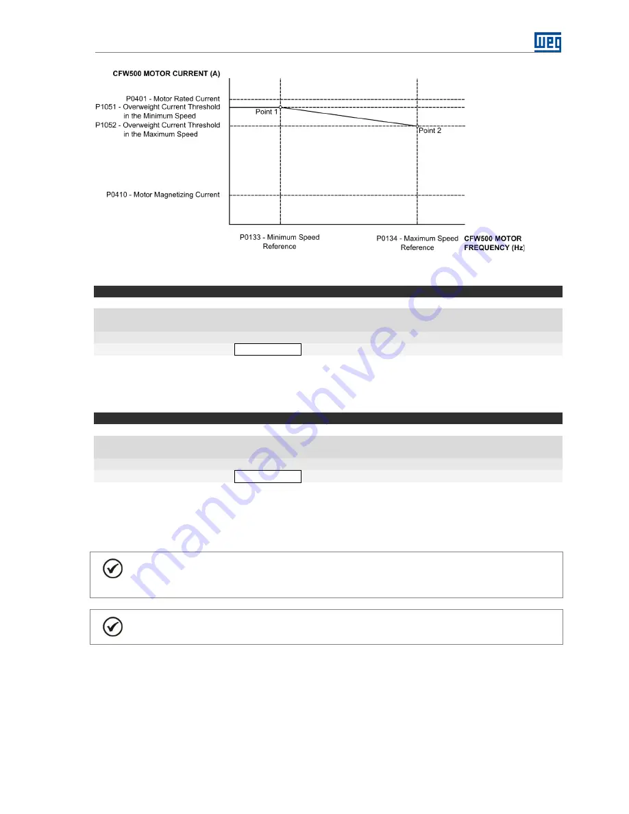
Figure 3.7 – Overweight curve 


P1053 – Overweight Detection Delay Time 


Adjustable


0.00 to 650.00 s 

Factory Setting:    

1.00 s 

Range:


Proprieties: 


Access groups via HMI: 

 SPLC   


Description: 

This parameter defines a delay time after the hoisting command has been given, before initiating the overweight 

monitoring according to the overweight curve defined in P1051 and P1052. 


P1054 – Overweight Alarm (A770) Delay Time 


Adjustable


0.00 to 650.00 s 

Factory Setting:    

0.50 s 

Range:


Proprieties: 


Access groups via HMI: 

 SPLC   


Description: 

This parameter defines a delay time after the motor current becomes greater than or equal to the overweight 

curve defined in P1051 and P1052, during a hoisting command, before the alarm “A770: Detected Overweight”, 

is generated. 


NOTE! 

With the overweight detection, an emergency stop is executed respecting the ramp defined in 

P0101. 


NOTE! 

The alarm is reset when a load lowering command is given for at least 100 ms.


The overweight detection operation diagram, considering that the crane vertical motion has been configured for 

two speed references obtained from the digital input logic, is presented next. Only the motor frequency  has 

been considered in the brake control logic. The digital output DO4 is used to indicate the overweight alarm. 


Содержание Crane CFW500 series

Страница 1: ...Motors Automation Energy Transmission Distribution Coatings Crane CFW500 Application Manual Language English Document 10004819846 01...

Страница 2: ......

Страница 3: ...Crane Application Manual Series CFW500 Language English Document Number 10004819846 01 Publication Date 04 2017...

Страница 4: ...18 2 3 CONTROL CONNECTIONS 18 2 3 1 Speed Reference via Electronic Potentiometer EP 19 2 3 2 Speed Reference via Digital Inputs 20 2 3 3 Speed Reference via Analog Input AI1 22 2 3 4 Speed Reference...

Страница 5: ...NG 70 3 19 READ ONLY PARAMETERS 70 3 19 1 Vertical 70 3 19 2 Horizontal 72 4 CREATION AND DOWNLOAD THE APPLICATION 75 5 DOWNLOAD DIALOG BOXES 80 6 PROJECT TREE ON WLP 81 6 1 LADDER DIAGRAMS 81 6 2 APP...

Страница 6: ...ed together with the CFW500 user manual the SoftPLC function manual and the WLP software manual ABBREVIATIONS AND DEFINITIONS PLC Programmable Logic Controller CRC Cycling Redundancy Check RAM Random...

Страница 7: ...CableFault Bit12 InverterinTorqueLimit Bit13 ImproperOperation Bit14 Reserved Bit15 Reserved ro SPLC 71 P1022 Communication Network Control Word Bit0 LoadHoisting Bit1 LoadLowering Bit2to15 Reserved 0...

Страница 8: ...A 0 0 A SPLC 51 P1044 Load Hoisting Torque Threshold 0 0 to 350 0 50 0 SPLC 51 P1045 Load Lowering Torque Threshold 0 0 to 350 0 30 0 SPLC 51 P1046 Brake Response Time to Release 0 00 to 650 00 s 0 10...

Страница 9: ...er Operation Bit14 Reserved Bit15 Reserved ro SPLC 74 P1022 Communication Network Control Word Bit0 Load Forward Bit1 Load Reverse Bit2to15 Reserved 0 rw SPLC 33 P1023 Speed Reference Control Configur...

Страница 10: ...0 0Hz 4 0 Hz SPLC 51 P1043 CurrentThresholdtoReleasetheBrake 0 0to200 0A 0 0 A SPLC 55 P1045 TorqueThresholdReleasetheBrake 0 0to350 0 0 0 SPLC 56 P1046 Brake Response Time to Release 0 00to650 00s 0...

Страница 11: ...o the user that the parameters related to the brake release command were programmed incorrectly P1041 programmed with 0 and P1042 and P1044 or P1043 and P1045 also programmed with 0 A770 Detected Over...

Страница 12: ...o avoid material and personal damages The product was manufactured under strict quality control however if installed in systems where its failure causes risks of material or personal damages additiona...

Страница 13: ...regenerative becomes feasible making it possible besides the above mentioned energy savings for the return to the line of the energy regenerated by lowering and braking the load when the motor is bein...

Страница 14: ...ement factory sawmills fertilizer plants container handling etc Where the loading requests are on average more than 50 of the rated capacity Motor Load Motor Drive P P I I 30 1 Being IDrive frequency...

Страница 15: ...value of the braking resistor to be used according to the frequency inverter model NOTE If the power required by the load is unknown use the motor rated power considering the service fact to the dime...

Страница 16: ...rhead crane is 17 kW the used motor would be a 20 kW commercial value In this case the braking resistor can be obtained from the calculated power in other words 0 7 x 17 43 4 kW The installation condi...

Страница 17: ...analog input Mechanical brake release logic controlled by motor frequency and or motor current and or motor torque with independent settings for load hoisting and load lowering commands Adjust of the...

Страница 18: ...ed only by motor frequency total speed reference in Hz Possibility of brake closing delay time Adjust of the time to enable a new command to brake release after the command to brake closing preventing...

Страница 19: ...cy inverter manual and the CFW500 IOS installation guide for further details about connections Connector Default Function for Crane via Electronic Potentiometer EP 1 DI1 Upper Terminal Digital input 1...

Страница 20: ...he CFW500 frequency inverter manual and the CFW500 IOS installation guide for further details about connections Connector Default Function for Crane via Digital Inputs 1 DI1 Upper Terminal Digital inp...

Страница 21: ...tal input 1 Load Hoisting Forward Command 3 DI2 Digital input 2 Load Lowering Reverse Command 5 DI3 Digital input 3 Emergency Stop 7 DI4 Digital input 4 1st DI for Speed Reference 9 24V Power supply 2...

Страница 22: ...inverter manual and the CFW500 IOS installation guide for further details about connections Conector Default Function for Crane via Analog Input AI1 DI1 Upper Terminal Digital input 1 Load Hoisting F...

Страница 23: ...orks 1 DO1 RL NO Upper Terminal Relay digital output 1 DO1 Brake Release 3 DO1 RL C 5 DO3 RL NO Relay digital output 3 DO3 No Fault 7 DO3 RL C 9 DO4 RL NO Relay digital output 4 DO4 Run 11 DO4 RL C 13...

Страница 24: ...s that filter undesirable voltage spikes and enable fast current shutdown NOTE It is recommended always power the brake by direct current DC as it provides greater speed and reliable brake operation 2...

Страница 25: ...he direct current source to terminals 3 and 04 keeping the terminals 1 and 2 on AC power supply Figure 2 7 Connection diagram of the bridge rectifier for fast braking 2 4 1 2 DC Power Supply The conne...

Страница 26: ...he inverter control in LOCAL situation is done via HMI and in REMOTE situation via SoftPLC function LOCAL Situation It allows the user to command the motor of crane driven by the CFW500 inverter disre...

Страница 27: ...work to prevent too fast or false commands are accepted by the crane vertical or horizontal motion With the value in 0 00 s disabled there is no filter on the digital inputs DI1 and DI2 With the value...

Страница 28: ...aximum speed defined in P0134 P0101 Deceleration Time Adjustable 0 0 to 999 0 s Factory Setting 2 0 s Range Proprieties Access groups via HMI BASIC Description This parameter defines the time to decel...

Страница 29: ...scription This parameter defines the minimum motor speed reference value when the inverter is enabled It is the value used when the limit switch Hoisting Forward Reverse Slowdown is activated P0134 Ma...

Страница 30: ...nds 3 It defines that there will be three speed references controlled through the logic combination of the load hoisting forward load lowering reverse 1st digital input for speed reference DI4 and 2nd...

Страница 31: ...via HMI SPLC Description This parameter has different functions according to the speed reference control configuration P1023 0 it defines the minimum speed reference value for the crane In other word...

Страница 32: ...0 Hz Range P1023 1 0 0 Hz P1023 2 0 0 Hz P1023 3 60 0 Hz P1023 4 40 0 Hz P1023 5 30 0 Hz P1023 6 0 0 Hz P1023 7 0 0 Hz Proprieties Access groups via HMI SPLC Description This parameter has different f...

Страница 33: ...after the brake release I e maintains the speed reference 1 for a while even if another speed has been selected by the user 3 6 CONTROL WORD P1022 Communication Network Control Word Adjustable 0000h t...

Страница 34: ...execution of the commands for the crane vertical motion applicative 3 7 2 Horizontal P1025 Limit Switches Configuration Adjustable 0 Without Limit Switches Factory Setting 0 Range 1 Forward Slowdown...

Страница 35: ...scription This parameter defines that the function of the digital input DI1 will be the load hoisting command which enables the motor to run in the forward rotation direction or the reverse direction...

Страница 36: ...cy Stop It defines that the stopping operation will occur according to the deceleration ramp that has been programmed in P0103 With logical level 0 it executes the emergency stop command by decelerati...

Страница 37: ...lowering the load can be executed Emergency Stop It defines that the stopping operation will occur according to the deceleration ramp that has been programmed in P0103 With logical level 0 it executes...

Страница 38: ...be the 1st digital input for the selection of the crane vertical motion speed reference via the logical combination of digital inputs as described in the section 3 5 P1023 6 or 7 and P1025 0 1 2 3 4 o...

Страница 39: ...not actuated it allows commands for load hoisting or lowering P0270 DI8 Function Adjustable 0 to 46 0 Not Used Factory Setting 0 Range Proprieties CFG Access groups via HMI I O Description This param...

Страница 40: ...celerated down to 0 Hz in the shortest possible time With logical level 0 it executes the fast stop command with null deceleration ramp so that the crane horizontal motion motor stops in the shortest...

Страница 41: ...al motion is enabled so that a command for forward or reverse the load can be executed Fast stop It defines that the stopping operation will be carried out with a null deceleration ramp so that the mo...

Страница 42: ...rd or a load reverse command is executed the motor is accelerated to the value programmed in P1031 Then if an acceleration command is given the motor is accelerated from the P1031 value up to the maxi...

Страница 43: ...define that the function of the D7 is Forward Slowdown Limit Switch when P1025 1 With logical level 0 sensor actuated and with a forward command present it decelerates the motor down to the minimum sp...

Страница 44: ...tion 1 Factory Setting P0276 13 Range 38 Overweight Application Function 2 P0277 11 39 Slack Cable Application Function 3 P0278 0 40 Torque Limitation Application Function 4 P0279 0 Proprieties Access...

Страница 45: ...able 0 to 44 37 Brake Release Application Function 1 Factory Setting P0276 13 Range 38 Momentary Overload Application Function 2 P0277 11 40 Torque Limitation Application Function 4 P0279 0 Proprietie...

Страница 46: ...Factory Setting 0 Range 1 4 to 20 mA Proprieties Access groups via HMI I O Description This parameter configures the type of signal voltage or current that will be read by the analog input AI1 NOTE Re...

Страница 47: ...t operation mode the motor speed reference will be the maximum value programmed in parameter P0134 3 11 1 Vertical P1037 Hoisting Current Threshold for Lightweight Detection P1038 Lowering Current Thr...

Страница 48: ...t in P1031 3 The speed reference 2 programmed in P1032 is selected through the digital input DI4 and the load is then accelerated to that speed Note that the motor current remains below the lightweigh...

Страница 49: ...ates that it is with lightweight P1039 Speed Threshold for Lightweight Detection Enabling Adjustable 0 0 to 500 0 Hz Factory Setting 0 0 Hz Range Proprieties Access groups via HMI SPLC Description Thi...

Страница 50: ...8 4 At that moment the motor frequency crosses the speed threshold for lightweight detection adjusted in P1039 and because the motor current remains below the current threshold set in P1038 lightweigh...

Страница 51: ...0 A Factory Setting P1042 0 0 A Range P1043 0 0 A Proprieties Access groups via HMI SPLC Description These parameters define the motor current thresholds to release the brake with hoisting P1042 or lo...

Страница 52: ...HMI SPLC Description This parameter inhibits the brake closing during the transition from hoisting to lowering and vice versa NOTE Available when a vector with encoder control mode is chosen P0202 4 P...

Страница 53: ...d thus the brake can be released again thus preventing a new command to be generated without the brake being closed mechanically NOTE The value of the set time should be sufficient to ensure that a ne...

Страница 54: ...put DI1 The motor becomes magnetized and voltage and frequency are applied to it The brake remains closed 2 The motor current reaches the P1042 threshold the brake however remains closed because the m...

Страница 55: ...cal brake is executed through the removal of the digital output DO1 command in this instant starts elapsing the time to enable a new command to brake release P1050 11 The motor is decelerated down to...

Страница 56: ...ing this parameter in 0 0 disables the motor torque verification for the brake control P1046 Brake Response Time to Release Adjustable 0 00 to 650 00 s Factory Setting 0 10 s Range Proprieties Access...

Страница 57: ...ke Release Adjustable 0 10 to 650 00 s Factory Setting 0 20 s Range Proprieties Access groups via HMI SPLC Description This parameter defines a time after the command to brake closing has been execute...

Страница 58: ...ital output DO1 The brake control operation diagram considering that the crane horizontal motion has been configured for two speed references obtained from the digital input logic and that the evaluat...

Страница 59: ...The motor current reaches the P1043 threshold the brake however remains closed because the motor frequency is below the frequency threshold adjusted in P1041 3 The motor current remains greater than o...

Страница 60: ...d hoisting stage Overweight is an abnormal condition detected during the hoisting stage of the crane vertical motion operation It indicates that the load weight is greater than the maximum established...

Страница 61: ...ion This parameter defines a delay time after the motor current becomes greater than or equal to the overweight curve defined in P1051 and P1052 during a hoisting command before the alarm A770 Detecte...

Страница 62: ...and the command to release the mechanical brake through the digital output DO1 is executed Overweight detection delay time programmed in P1053 starts elapsing because the load hoisting and brake rele...

Страница 63: ...or load reverse stage Momentary Overload is an abnormal condition detected during the crane horizontal motion operation where during the command to load forward or load reverse it appears that a furt...

Страница 64: ...the motor current becomes greater than or equal to the threshold defined in P1052 during a load forward or load reverse command before the alarm A770 Momentary Overload is generated The momentary over...

Страница 65: ...or deceleration begins The brake remains release 9 The motor frequency becomes less than or equal to the threshold adjusted in P1048 and the command to close the mechanical brake is executed through t...

Страница 66: ...650 00 s Factory Setting 0 00 s Range Proprieties Access groups via HMI SPLC Description This parameter defines a delay time after it has been detected that the motor is being driven by the inverter w...

Страница 67: ...e applied to it The brake remains closed 2 The motor frequency reaches the threshold adjusted in P1041 and the command to release the mechanical brake through the digital output DO1 is executed 3 The...

Страница 68: ...in the crane motion operation when the CFW50 frequency inverter is not able to execute the motion in the desired manner with controlled speed i e operating in a torque limit condition NOTE The invert...

Страница 69: ...75 Inverter in Torque Limit is generated 3 17 IMPROPER OPERATION This parameter group allows to the user to adjust the conditions to supervise the use of the crane motion verifying whether it is being...

Страница 70: ...19 1 Vertical P1010 Crane Vertical Motion Version Adjustable 0 00 to 10 00 Factory Setting Range Proprieties RO Access groups via HMI SPLC Description This parameter indicates the version of the appli...

Страница 71: ...tion 1 Motor in forward speed direction Bit 3 LOC REM 0 Inverter in local mode 1 Inverter in remote mode Bit 4 Fault Condition 0 The inverter is not in a fault condition 1 The inverter has detected a...

Страница 72: ...m indication 1 It indicates that the hoisting slowdown limit switch has been actuated A760 Bit 6 Reserved Bit 7 Reserved Bit 8 ProgrammingErrorRelease Brake 0 No alarm indication 1 It indicates that t...

Страница 73: ...nd Alarm Condition Undervoltage Fault Condition LOC REM Rotation Direction Running General Enabled Bits Values Bit 0 General Enabled 0 The inverter is general disabled 1 The inverter is general enable...

Страница 74: ...on is in the lightweight operation mode A750 Bit 1 Coast to Stop 0 No alarm indication 1 The general enable signal has been removed from the DI3 causing the motor to cast down A752 Bit 2 Fast Stop 0 N...

Страница 75: ...zard The following steps show how to create and configure the Crane application in the WLP and how to transfer it to the CFW500 inverter NOTE The Crane application only works on CFW500 inverter with f...

Страница 76: ...pment can be via USB or serial port COM1 COM8 For this select Communicate and then click Configuration Shift F8 Figure 4 3 Adjust the communication interface in the new project 4th Step Download the l...

Страница 77: ...the CFW500 frequency inverter In order to do so after the project is compiled and the CFW500 frequency inverter identified click on Start to start transferring Figure 4 6 User s program and user s par...

Страница 78: ...ation For this click the Configuration Wizard Crane Vertical Motion or Crane Horizontal Motion in the project tree bar Figure 4 8 Select the configuration wizard for Crane 9th Step Click Finish in the...

Страница 79: ...s configured in the configuration wizard of Crane application for the CFW500 inverter For this click Yes to start sending the values Figure 4 10 Dialog for download the values of configuration wizard...

Страница 80: ...the User Parameters User program download dialog box containing Characteristics of the connected equipment Name of the file to be downloaded Size of the application to be downloaded File compilation d...

Страница 81: ...les through the Monitoring Dialogs 3 monitor variables through Trend Variables Dialogs 4 and upload download drive parameters CFW500 through the parameter Values Dialogues 5 The figure 6 1 presents th...

Страница 82: ...Configuration wizard for Crane Vertical or Horizontal Motion application 6 2 1 Tittle The page title indicates that the feature is covered 6 2 2 Input Value for Parameters The input values for the par...

Страница 83: ...he WLP Figure 6 4 Monitoring dialog of the Crane Vertical or Horizontal Motion application 6 4 TREND VARIABLES DIALOG BOXES It is possible to monitor variables of the Crane Vertical or Horizontal Moti...

Страница 84: ...ugh the WLP it is possible to save the parameters of the Crane Vertical or Horizontal Motion applicative Figure 6 6 Parameter value dialog NOTE Refer to the WLP programming software help topics for mo...

Отзывы: