


Flameproof motors | 31
www.weg.net
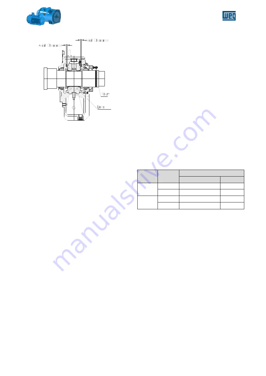
Figure 5-17 - Drive end sleeve bearing
5.1.6. COOLING
During installation, all cooling conditions should be
considered.
The
recommended
installation
distance between air inlet into the motor and the
wall should be at least ¼ of the air inlet diameter. A
person should also be able to move between the
motor and the wall to carry out cleaning services on
the air inlet screen.
Machines that are cooled with ambient air, air inlet
screens or tubes must be cleaned at regular
intervals so as to ensure free passage of air. The
warm air can not be sucked again by the motor.
- Vertically mounted motors with air inlet on top:
the air opening must be protected by a proper
cover so as to avoid dropping of foreign
materials vertically into the motors.
- All protections provided for transportation and
storage of the machine should be removed right
before the installation.
- Considering that direct sun heat causes
increase in temperature, externally installed
motors should be always protected against
weathering.
- A good housekeeping for ribs and tubes must
be guaranteed to avoid dust or other corps
deposition.
5.1.7. VIBRATION / BALANCE
All WEG motors and generators are dynamically
balanced with half key;
They are balanced and are in conformity with
vibration limits established by IEC 60034-14
standard (except when the purchasing agreement
specified different values).
At factory, vibration measurements are performed
on the drive and non-drive end bearings, vertically,
horizontally and axially.
When a customer supplies the half coupling sleeve
to WEG, the motor is balanced with this half sleeve
mounted to the shaft. When this is not the case,
based on the above standards motor is balanced
with half key (that is, the key way is fulfilled with a
piece of metal of identical width, thickness and
height of the keyway).
The
maximum
allowable
vibration
levels
recommended by WEG for motors in operation are
according to ISO 10816-3 Standard. This standard
classifies the support class as rigid:
if the lowest
natural frequency of the combined machine and
support system in the direction of measurement is
higher than its main excitation frequency (this is in
most cases the rotational speed/frequency) by at
least 25% then the support system may be
considered rigid in that direction. All other support
systems may be considered flexible.
The
maximum
allowable
vibration
levels
recommended by WEG for motors in operation are
given on the table below. These values are generic
and serve as a guideline. Specific application
conditions must be taken into consideration.
Table 5-4 - ISO 10816-3 vibration limits
Suport
class
Zone
Boundary
Velocity (mm/s R.M.S.)
160mm < H < 315mm
H ≥ 315mm
Rigid
Alarm
3,5
5,5
Trip
4,5
7,1
Flexible
Alarm
5,5
8,8
Trip
7,1
11,0
Vibration causes most frequently found on the field
are:
- Misalignment between motor and driven
machine;
- Incorrect motor fastening to the base, with
“loose shims” underneath one or more motor
feet and studs incorrectly fastened;
- Improper base, or not firmly built;
- External vibrations caused by other equipment.
Operate the motor with vibration values above
those described in the Table 5-4 can damage its
lifetime and/or its performance.
5.1.8. SHAFT VIBRATION LIMITS
In motors equipped or foreseen for installation of
proximitor sensor (normally used in sleeve bearing)
the shaft surfaces are prepared with special
finishing in the adjacent areas of the bearings, so
as to ensure the correct shaft vibration
measurement.
The shaft vibration in these motors is measured
and must comply with IEC 60034-14 Standard.