9-8 | MVW3000
9
Communication Networks
9-8 | MVW3000
9.1.6.1 Variables Read From the Inverter
1. Inverter logical status.
2. Motor speed, for the option P0309 = 1 or 4 (2I/O) - read 1 and 2.
3. Digital input status (P0012).
4. Parameter contents, for the option P0309 = 2 or 5 (4I/O) - read 1, 2, 3 and 4.
5. Parameter contents, for the option (P0009).
6. Motor current (P0003), for the option P3009 = 3 or 6 (6I/O) - read 1, 2, 3, 4, 5 and 6.
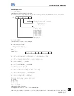
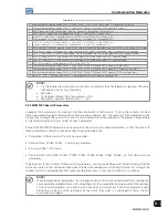
1. Status word (EL):
The status word is composed by a total of 16 bits, 8 high order bits and 8 low order bits. It has the following
construction:
High-order bits - they indicate the status of the associated function.
EL.15 - Active error: 0 = No, 1 = Yes.
EL.14 - PID Regulator: 0 = Manual, 1 = Automatic.
EL.13 - Undervoltage of the electronics power supplies: 0 = Without, 1 = With.
EL.12 - Local/Remote command: 0 = Local, 1 = Remote.
EL.11 - JOG command: 0 = Inactive, 1 = Active.
EL.10 - Forward/Reverse: 0 = Reverse, 1 = Forward.
EL.09 - General enabling: 0 = Disabled, 1 = Enabled.
EL.08
(*)
- Start/Stop: 0 = Stop, 1 = Start.
(*)
O EL.08 = 1, means the inverter received the Run/Stop command via networks. This EL is not intended to signal that the motor is
effectively spinning.
Low-order bits -they indicate the error code number, i.e., 03, 07 or 87 (57h).
For further information on the faults and alarms, refer to the programming manual available for download on:
www.weg.net
.
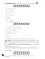
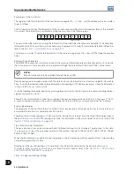
2. Motor speed:
This variable is shown by using 13-bit resolution plus signal. Thus, the rated value will be equal to 8191 (1FFFh)
(Forward) or -8191 (E001h) (Reverse) when the motor is running at synchronous speed (or base speed, for
instance 1800 rpm for a IV-pole motor, 60 Hz).
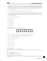
3. Digital input status:
It presents the parameter P0012 contents, where 1 indicates an active input and 0 indicates an inactive input.
For further information on parameters, refer to the programming manual available for download on:
www.weg.net
.
The digital inputs of this WORD are distributed as follows:
Bit.7 - DI1 status.
Bit.2 - DI6 status.
Bit.6 - DI2 status.
Bit.1 - DI7 status.
Bit.5 - DI3 status.
Bit.0 - DI8 status.
Bit.4 - DI4 status.
Bit.8 - DI9 status.
Bit.3 - DI5 status.
Bit.9 - DI10 status.
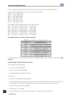
4. Parameter contents:
This position allows reading the contents of inverter parameters, which are selected at the position 4 - Number
of the parameters to be read - of the variables written in the inverter. The read values have the same order of
magnitude of those described in the product manual or showed on the HMI.
The values are read without the decimal point, if that is the case.
Examples:
1. HMI displays 12.3, the Fieldbus reading will be 123.
2. HMI displays 0.246, the Fieldbus reading will be 246.
Содержание MVW3000 A0040 V023
Страница 2: ......
Страница 4: ......
Страница 5: ...User s Manual Series MVW3000 Language English Document 10004823674 00 Publication Date 03 2017...
Страница 6: ...Summary of Reviews Version Review Description R00 First edition...
Страница 12: ...1 4 MVW3000 1 Safety Notices...
Страница 58: ...6 18 MVW3000 6 Installation Connection and Energization...
Страница 88: ...8 10 MVW3000 8 8 Special Functions...


