9-2 | MVW3000
9
Communication Networks
9-2 | MVW3000
4. Press the board close to XC140 and on the bottom right corner until the complete insertion of the connector
and the plastic spacer.
5. Secure the board to the metallic spacers with the provided bolt.
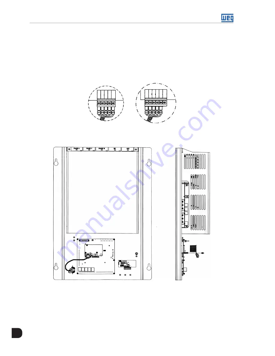
6. Connect one end of the Fieldbus cable to the MVW3000 control rack, according to the
Figure 9.3 on page
9-2
.
7. Connect the other end of the Fieldbus cable to the Fieldbus board, according to the
Figure 9.3 on page 9-2
.
DEVICENET
PROFIBUS DP
1
1
2
2
3
3
4
4
5
5 6
Figure 9.2:
Connection to the Fieldbus board
Figure 9.3:
Connection to the Fieldbus board
9.1.2 Profibus DP
The inverter that is fitted with the Profibus DP Kit operates in slave mode, allowing the reading/writing of its
parameters through a master. The inverter does not start the communication with other nodes, it only answers
to the master controls. The physical medium uses a two-conductor twisted-pair cable (RS-485) allowing data
transmission at baud rates between 9.6 kbits/s and 12 Mbits/s. The
Figure 9.4 on page 9-3
shows an overview
of a Profibus DP network.
Содержание MVW3000 A0040 V023
Страница 2: ......
Страница 4: ......
Страница 5: ...User s Manual Series MVW3000 Language English Document 10004823674 00 Publication Date 03 2017...
Страница 6: ...Summary of Reviews Version Review Description R00 First edition...
Страница 12: ...1 4 MVW3000 1 Safety Notices...
Страница 58: ...6 18 MVW3000 6 Installation Connection and Energization...
Страница 88: ...8 10 MVW3000 8 8 Special Functions...


