9-10 | MVW3000
9
Communication Networks
9-10 | MVW3000
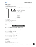
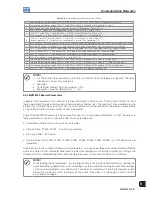
NOTE!
The inverter will only execute the command defined in the low-order bit if the correspondent high-
order bit is set to 1 (one). If the high-order bit is set to 0 (zero), the inverter will disregard the value
of the correspondent low-order bit.
CL.13: The function of saving parameter content changes in the EEPROM occurs normally when the
HMI is used. The EEPROM allows a limited number of writings (100.000). In applications in which
the speed regulator remains saturated and torque control is required, this control can be achieved
by adjusting the torque limits P169/P170 (valid for P202 > 2). Therefore, if the network master keeps
writing continuously in P169/P170, then the correspondent bits must be programmed in order to
avoid that every change be saved in the EEPROM by setting: CL.13 = 1 and CL.5 = 1.
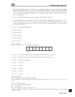
In order to enable the functions of the Control Word, it is necessary to set the inverter respective parameters with
the option “Fieldbus”.
a) Local/Remote Selection Source - P0220.
b) Speed Reference - P0221 and/or P0222.
c) Forward/Reverse Selection - P0223 and/or P0226.
d) General Enabling, Start/Stop Selection - P0224 and/or P0227.
e) JOG Selection - P0225 and/or P0228.
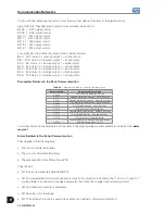
2. Motor speed reference:
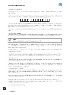
This variable is presented using a 13 bit resolution. Therefore, the speed reference value for the motor synchronous
speed will be equal to 8191 (1FFFh).
This value must be used only as the base speed for the calculation of the desired speed (speed reference).
Examples:
1. 4-pole, 60 Hz motor, synchronous speed = 1800 rpm and speed reference = 650 rpm.
1800 rpm - 8191
650 rpm - X
X = 2958 = 0B8Eh
This value (0B8Eh) must be written in the second word, which represents the motor speed reference (according
to the beginning of this item).
2. 6-pole, 60 Hz motor, synchronous speed = 1200 rpm and speed reference = 1000 rpm.
1200 rpm - 8191
1000 rpm - X
X = 4096 = 1AAAh
This value (1AAAh) must be written in the second word, which represents the motor speed reference (according
to the beginning of this item).
NOTE!
Values above 8191 (1FFFh) are allowed when speed references above the motor synchronous speed
are required, as long as the maximum programmed speed reference is respected.
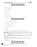
3. Status of the digital outputs:
It allows controlling the status of the digital outputs that have been programmed for Fieldbus at the parameters
P0275 to P0282. 16 bits, with the following construction, form the word that defines the status of the digital
outputs:
High-order bits: they define the outputs to be controlled, when set in 1.
Bit.08: 1 - DO1 output control.
Bit.09: 1 - DO2 output control.
Bit.10: 1 - RL1 output control.
Bit.11: 1 - RL2 output control.
Bit.12: 1 - RL3 output control.
Low-order bits: they define the status of the controlled outputs.
Bit.0 - DO1 status: 0 = inactive output, 1 = active output.
Bit.1 - DO2 status: idem.
Содержание MVW3000 A0040 V023
Страница 2: ......
Страница 4: ......
Страница 5: ...User s Manual Series MVW3000 Language English Document 10004823674 00 Publication Date 03 2017...
Страница 6: ...Summary of Reviews Version Review Description R00 First edition...
Страница 12: ...1 4 MVW3000 1 Safety Notices...
Страница 58: ...6 18 MVW3000 6 Installation Connection and Energization...
Страница 88: ...8 10 MVW3000 8 8 Special Functions...


