53 |
P a g e
T-POSTS INSTALLATION ALIGTMENT BLOCK WITH
3-SIDED FRAME MOUNTING ON WINDOW SILL
1.
ATTACH T-POST BLOCKS TO FRAME
•
Stack two T Post Alignment Blocks, both with the tabs facing down.
•
Lay out the top frame so that the light block is facing up.
•
Two holes have been pre-drilled diagonally in the face of the top frame at each
T-Post location.
•
Position the stacked blocks on the light block portion of the frame so that the
holes in the block align with the pre-drilled holes in the frame. (The tabs will hang
off the edge of the light block.)
•
Using (2) #6 x 44mm T Post block screws, attach the blocks to the frame. Do not
completely tighten the screws down, only make them snug. This will allow some
side-to-side adjustment of the T Post
2.
ASSEMBLE FRAME AND T-POST
•
Insert the corner keys into the top frame.
•
Attach the left side frame to the top frame.
•
Attach the right side frame to the top frame.
•
Attach T Post to the top frame by sliding the T-Post over the blocks on the top
frame.
3.
BEGIN INSTALLING THE SHUTTER
•
Begin by installing the shutter as a standard 3-sided frame but install only the top
screw on each side frame and one bottom screw if necessary.
•
Test the fit and position of the panels to determine the location of the T Post.
•
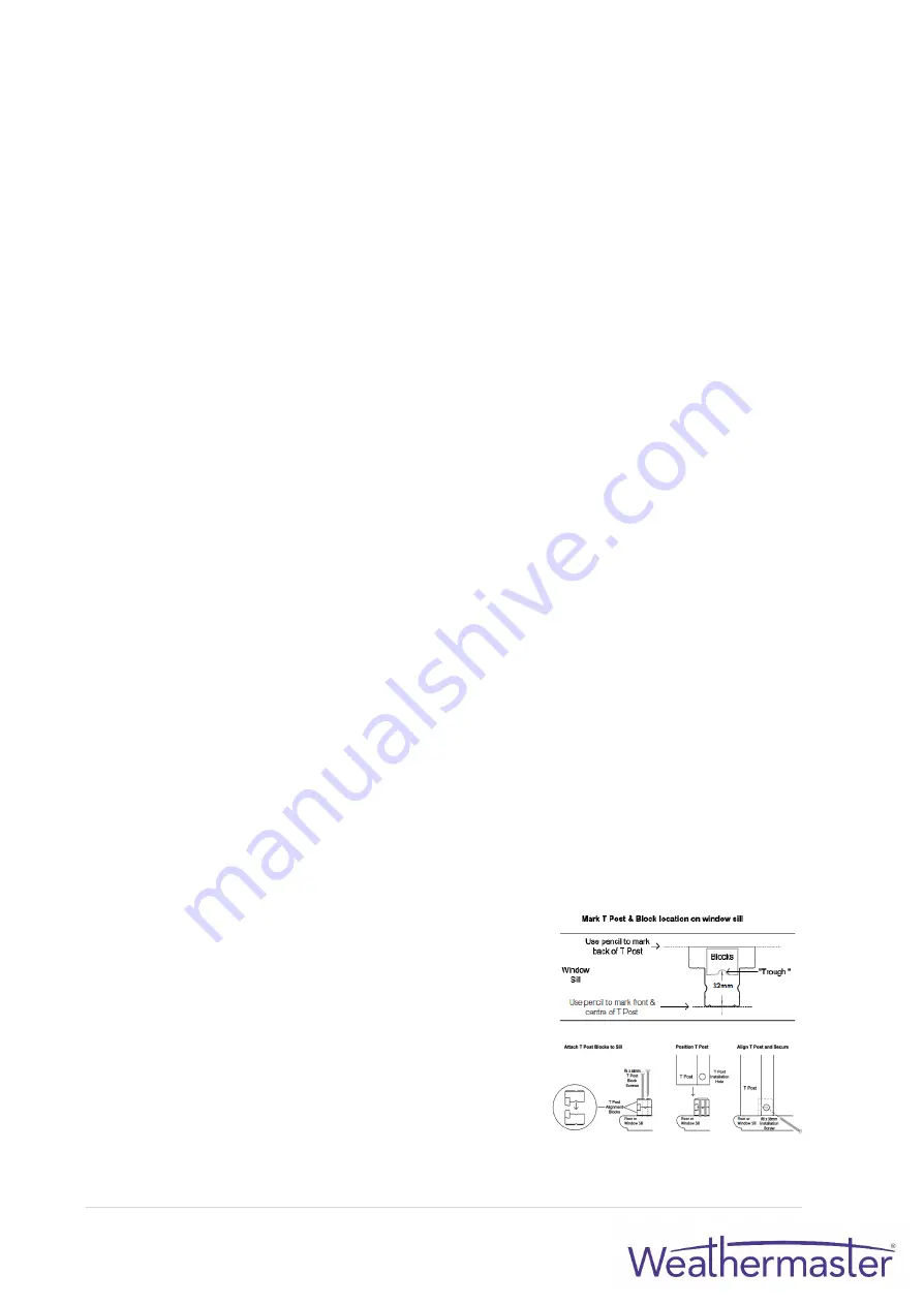
Mark the front and centre of the T Post with a pencil on the sill.
•
Mark the back of the T Post with a pencil on the sill.
•
Remove the panels and the frame.
•
Stack two T Post Alignment Blocks, one with the tab facing up and one with the
tab facing down (as pictured below).
•
Attach tw
o stacked T Post blocks to the sill so that the back of the “trough” of the
block is 32mm from the front centre mark of the T Post.
•
Use (2) #6 x 44mm T Post Block Screws to attach the blocks to the sill. Do not fully
tighten the screws - they should only be snug.
•
Set the assembled frame back in the opening making sure the bottom of the T
Post slides over the blocks on the sill.
•
Finish installing the frame and then hang the
panels.
4.
ALIGN T-POST AND SECURE
•
Determine the side-to-side position of the T-Post,
then drive a #8 x 38mm installation screw
horizontally through the hole in the end of the T
Post.
•
The screw will then pass between the (2) T-Post
Blocks, thus locking the T-Post into position.
•
Repeat for the top of the T Post and cap
installation holes with button covers
.
Содержание Eclipse Shutters
Страница 1: ...Eclipse Shutters Installation Manual ...
Страница 3: ...3 P a g e GENERAL INFORMATION SHUTTER PANEL PARTS DIAGRAM ...
Страница 5: ...5 P a g e SHUTTER PANEL PARTS ...
Страница 15: ...15 P a g e SLIDING OPEN SLIDING SHUTTERS TRACK SYSTEM SLIDING SHUTTERS TRACK SYSTEM DIAGRAM ...
Страница 16: ...16 P a g e SLIDING SHUTTERS TRACK SYSTEM DIAGRAM OPEN SLIDING ...
Страница 20: ...20 P a g e SLIDING SHUTTERS RECESS MOUNT APPLICATION ...
Страница 21: ...21 P a g e SLIDING SHUTTERS RECESS MOUNT APPLICATION ...
Страница 22: ...22 P a g e SLIDING SHUTTERS FACE MOUNT APPLICATION ...
Страница 23: ...23 P a g e SLIDING SHUTTERS FACE MOUNT APPLICATION ...
Страница 27: ...27 P a g e TRIPLE SLIDING SHUTTERS TRACK SYSTEM DIAGRAM ...
Страница 30: ...30 P a g e SLIDING SHUTTERS RECESS MOUNT APPLICATION ...
Страница 31: ...31 P a g e SLIDING SHUTTERS FACE MOUNT APPLICATION ...
Страница 35: ...35 P a g e BI FOLD TRACK SYSTEM DIAGRAM Clearance 15mm Internal Tracks Nominal ...
Страница 38: ...38 P a g e BI FOLD SHUTTERS DIAGRAM D FACE MOUNT ...
Страница 39: ...39 P a g e BI FOLD SHUTTERS DIAGRAM E RECESS MOUNT ...
Страница 41: ...41 P a g e BI FOLD SHUTTERS FRAME EXTENSIONS ...
Страница 45: ...45 P a g e VALANCE RETURN OPTIONS RECESS MOUNT FULLY RECESSED FRAME SQUARE CUT VALANCE ...
Страница 46: ...46 P a g e FACE MOUNT STANDARD FULL LENGTH VALANCE RETURNS ...


