8 of 14
WX-501-0537 • 01.22
feet between the location of the SmartSensor HD and the warning sign.
In order to trigger at a point upstream of a sign:
1. Select the Automatic (English) configuration options.
2. Specify the corresponding setback distance in feet. In this case, the setback distance is from the location of
the SmartSensor HD unit to the selected trigger point (upstream of the warning sign).
3. Specify the duration in milliseconds.
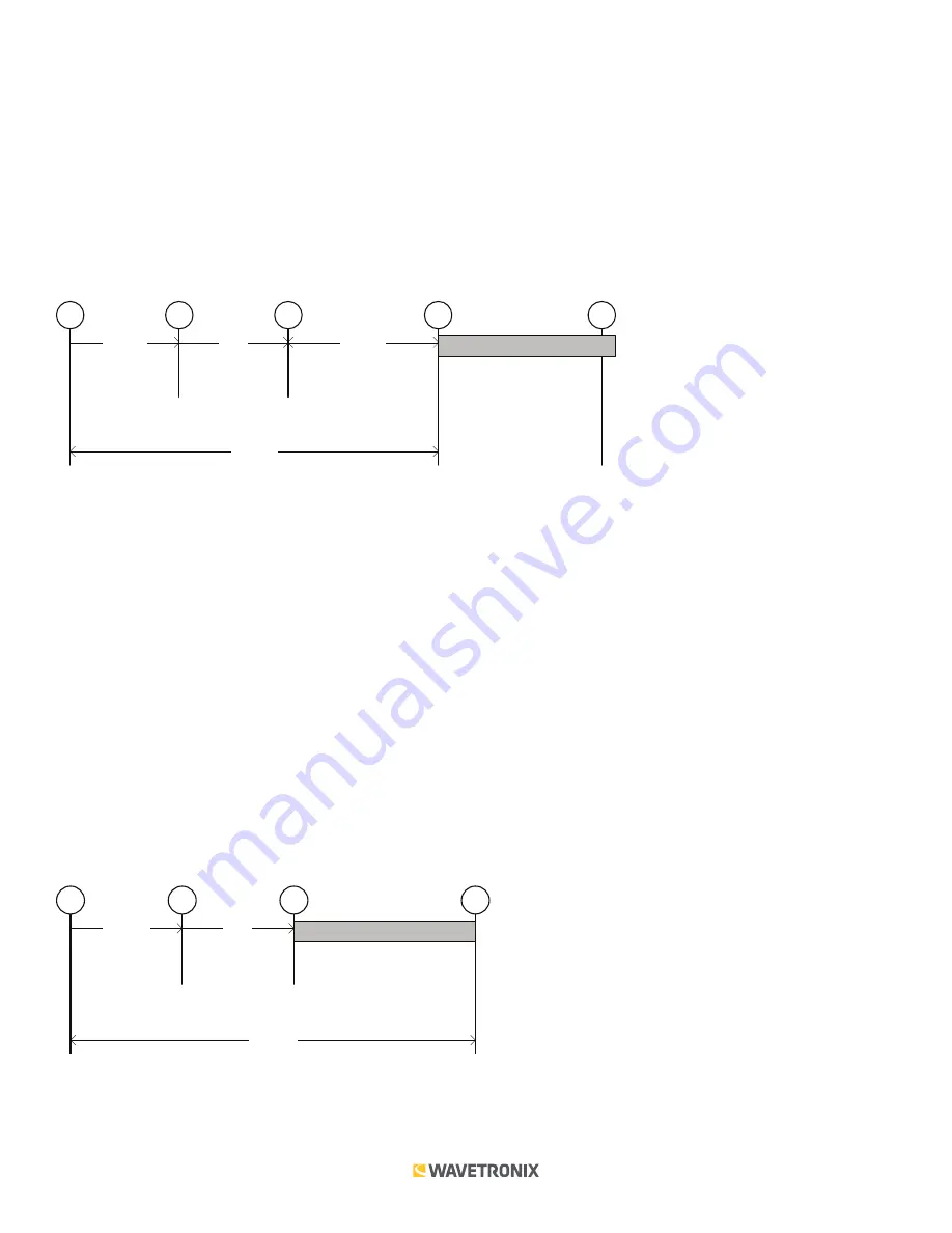
The following diagram illustrates the basic timing of this option as a series of 5 steps. Some portions of the timing
are variable and others are fixed.
variable
L_ft / V_fps
fixed
1 s
variable
Duration (fixed)
1
2
3
4
5
variable
Time to Point = SetbackDistance_ft / V_fps
1. Front edge of vehicle enters beam.
2. Back edge of vehicle leaves beam. The time from point 1 to point 2 is variable and is based on the length and
speed of the vehicle.
3. Detection event is generated one second after the vehicle leaves the beam. This one-second delay is fixed.
4. Output is activated when front-edge of vehicle reaches the selected trigger point (assuming constant speed).
5. Output is deactivated at the end of the duration.
The third method, the ASAP trigger method, provides a less uniform response because the trigger is not
synchronized. However, this method may be useful when the setback distance is limited.
In order to trigger as soon as possible:
1. Select the None (Trigger Sync) configuration options.
2. Specify the duration in milliseconds.
The following diagram illustrates the basic timing of this option as a series of four steps. Some portions of the
timing are variable and others are fixed.
variable
L_ft / V_fps
fixed
1 s
Duration (fixed)
1
2
3
4
variable
Total Delay = L_ft / Vfps + 1 s
1. Front edge of vehicle enters beam.
2. Back edge of vehicle leaves beam. The time from point 1 to point 2 is variable and is based on the length and
speed of the vehicle.


