12
IOM-A-Deringer 40/40X/50/50X_6-8
2005
EDP#2916006
© 2020 Watts
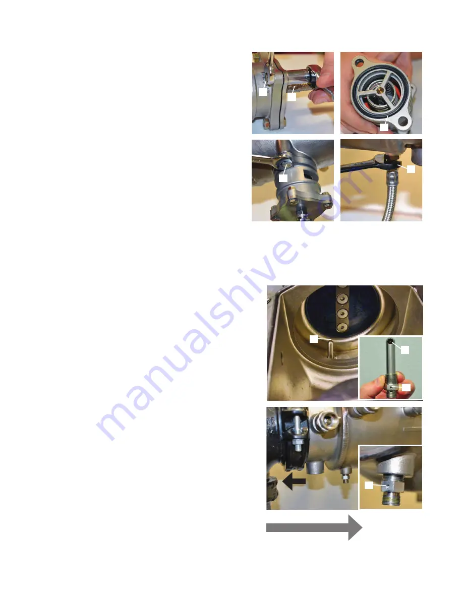
Maintenance of Relief Valve (continued)
D
1. Using two
7
/
16
" wrenches (A) re-attach the relief valve cover.
2. Making sure the relief valve O-ring (B) is in the groove on the top
of the relief valve use a
9
/
16
" wrench to re-attach the two relief
valve mounting bolts (C).
3. Use a
5
/
8
" box wrench re-connect the relief valve sensing line to
the valve (D).
C
A
B
A
Pitot Tube Orientation
1. Before reinstalling the relief valve after maintenance, check to make sure
the pitot tube (A) is in the proper orientation. If the pitot tube is
NOT
in
the proper orientation the relief valve
WILL LEAK OR DUMP
during
flow conditions.
2. The inlet port of the pitot tube (B) at the top of the pitot tube must face
directly UPSTREAM toward the #1 shutoff valve. Proper orientation can
be confirmed visually by removing the main line valve cover and first
check valve (see right).
3.
Note
that the inlet port of the pitot tube (B) is not visible because it is
facing directly upstream toward the #1 shutoff valve.
4. A dimple (C) has been provided on the hex wrench portion of the pitot
tube in order to visually confirm the proper orientation of the pitot tube
from the OUTSIDE of the valve (see right). Note that the dimple (C) is on
the same side of the pitot tube as the inlet port of the pitot tube (B) (see
above).
5. From the OUTSIDE of the valve the dimple (C) must face directly
UPSTREAM toward the #1 shutoff valve. If the dimple (C) of the pitot
tube is
NOT
in the oriented UPSTREAM the relief valve
WILL LEAK OR
DUMP
during flow conditions
A
C
B
C
FLOW
Upstream


