


Using the digital operator
Page 41 / 51
Function
Display *)
Function description / parameter setting range
Standard
setting
Set
values
Automatic Voltage Regulation (AVR)
The AVR function causes motor voltage stabilization when DC voltage is fluctuating (e.g. due to an instable mains
supply or a dropping or excessive DC voltage as a result of too short acceleration or deceleration times) and thus
ensures a high torque (especially during acceleration).
Dynamic braking (without the use of the AVR function) causes a rise in DC voltage during deceleration (especially
when very short deceleration times have been set) which in turn causes a rise in motor voltage. This raised motor
voltage causes a higher braking torque. For this reason, the AVR function can be deactivated for deceleration using
A 81
.
Charcteristics of
AVR function
A 81
N
00: AVR function active in every operation mode
01: AVR function is not active
02: AVR function is active in all operation modes except
deceleration
02
Motor voltage
for AVR function
A 82
N
The settable parameters depend on the inverter model used:
200V models: 200, 220, 230, 240 V
400V models: 380, 400, 415, 440, 460 V
If the mains supply voltage is higher than the rated motor
voltage, then the supply voltage must be entered here and the
output voltage must be reduced under
A 45
to the rated motor
voltage.
Example: With a mains supply voltage of 440V and a motor
rated voltage of 400V the parameter 440 has to be entered
under
A 82
and 91 (=400/440*100%) has to be entered
under
A 45.
FE models
230/400
FU models
230/460
Function
Display *)
Function description / parameter setting range
Standard
setting
Set
values
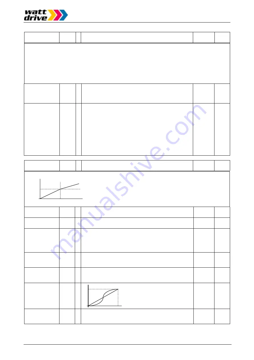
Time ramps
f
A 95
0
t
2CH or
A 95
Accel. 1
Accel. 2
2. Acceleration time
A 92
Y
Setting range: 0.1s–999,9s (Resolution 0.1s)
1000s–3000s (Resolution 1s)
15.0
2. Deceleration time
A 93
Y
Setting range: 0.1s–999,9s (Resolution 0.1s)
1000s–3000s (Resolution 1s)
15.0
Method to switch
over from 1. to 2.
accel/decel time
A 94
N
The switchover from the 1. acceleration / deceleration time to the
2.
acceleration / deceleration time is initiated by:
00: an active signal at a digital input configured as 2CH
01: the reaching of the frequencies set under
A 95
or
A 96
00
Accel.1 / Accel.2
switchover
frequency
A 95
N
Here the frequency is set at which the switchover from 1. to 2.
acceleration time must take place. Setting range: 0.0Hz–
360.0Hz.
0.0
Decel.1 / Decel.2
switchover
frequency
A 96
N
Here the frequency is set at which the switchover from 1. to 2.
deceleration time must take place. Setting range: 0.0Hz–
360.0Hz.
0.0
Acceleration
characteristic
A 97
N
f
0
t
linear
S curve
00
Deceleration
characteristic
A 98
N
A linear or an S curve characteristic can be chosen for motor
deceleration (1. and 2. deceleration times):
00: Linear
01: S curve
(also refer to
A 97
)
00
Содержание V2000 Series
Страница 1: ...INVERTER Series V2000 M A N U A L NB588XA...