background image


WL800 Manual 

                                                                         Page 34 – Revision 12-11-2018 


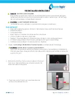
Flush Filters 


CAUTION!  

FILTER FLUSH REQUIRED. 


In order for our filters to perform as represented and to provide the best quality water possible, it 

is essential that filters be replaced periodically. The frequency of filter changes depends upon 

your water quality and your water usage. For example, if there is a lot of sediment and/or 

particles in your water, then you will have to change your filters more frequently than a location 

with little to no sediment. Be sure to replace your filters whenever you notice a decline in the 

performance, whether it is a drop in flow rate and/or pressure or an unusual taste in the water. 


4.


Flush thoroughly per filter manufacturers’ recommendation with fresh water to drain.  


5.


Once flushed, install the filters.  Following the flow direction on the filter. 


NOTE:


Filters should not be flushed prior to 24 hours before installation to limit Microbial Growth.   


Sanitizing 

Sanitize using a household bleach solution or other approved cleaner throughout the cold and sparkling 

water circuits.  Follow all instructions on the sanitizer and flush with fresh water through the faucet 

until odor and taste is acceptable. 


       WARNING!  

USE PROPER PERSONAL PROTECTIVE EQUIPMENT


Always ensure proper ventilation and use proper personal protective equipment such as gloves and 

eye protection when using chemicals.  Refer to Material Safety Data Sheet for specific requirements 

of each chemical product. Take all necessary precautions to prevent sanitizer from contacting eyes, 

clothing, and any other surfaces in could damage (carpets).   


6.


Connect 40-60 psi regulated, potable water supply to the water inlet bulkhead fitting located on the 

back of the unit.  Turn on water supply and check for leaks. 


      DANGER!  

ELECTRICAL SHOCK HAZARD.  

Do not plug in unit unless qualified.  Only qualified personnel who have read and understand this 

entire manual should attempt to install or service this unit.  


7.


Connect WL800 Water Treatment System to power and allow unit to fill completely. 


8.


Mix 2 liters (½ gallon) of sanitizer per directions or use Bleach Solution (1 teaspoon = 1/6 oz. = 5 ml = 

½ cap full) of household bleach (Sodium Hypochlorite 5 - 10% Concentration) with 1/2 gallon of 

water.  Always ensure sanitizer is compatible with stainless steel and acetal plastic. 


Содержание WL800 - MAX II

Страница 1: ...tonegate Circle Omaha NE 68164 800 288 1891 www waterlogicdealers com Tech Portal Website techportal waterlogic com Waterlogic International LTD Global Headquarters Grenfell Road Maidenhead Berkshire...

Страница 2: ...eat tasting water with every use TABLE OF CONTENTS Features and Benefits 3 Certifications 4 Introduction 5 Safety Alert Symbols 5 Safety Precautions 6 Model and Part Designations 7 Specifications 7 Op...

Страница 3: ...jogs and carafes Child Safeguard Hot Water safety feature to protect against accidental usage 4 Step Filtration System The Waterlogic WL800 Water Treatment System uses a 4 stage reverse osmosis RO to...

Страница 4: ...s been tested and certified in accordance with NSF ANSI 42 Drinking Water Treatment Units Aesthetics Effects NSF ANSI 53 Drinking Water Treatment Units Health Effects and NSF ANSI 58 Reverse Osmosis D...

Страница 5: ...ufactured and marketed by Waterlogic and its affiliates are protected by patents issued or pending in the United States and other countries Waterlogic reserves the right to change the specifications r...

Страница 6: ...be used for water only and is not intended for use where water is microbiologically unsafe or with water of unknown quality without adequate disinfection before or after the system The system is desi...

Страница 7: ...orking Pressure 60 psi 414 kPa Use Pressure Regulator Environmental Temperature 2 37 C 35 100 F Refrigerant Gas R134a 2 05 oz 65 grams Hi 290 psi Low 90 psi R134a Pressures High 290 psi Low 90 psi RO...

Страница 8: ...L800 Manual Page 8 Revision 12 11 2018 OPERATING INSTRUCTIONS Dispensing Water Cold Water Selection Push the cup touch Hot Water Selection Press the Hot Water Safety Button and push the cup touch leve...

Страница 9: ...UV recirculating system starts when the WL800 Water Treatment System is idle and unused for one hour The UV system will operator for 1 hour every 4 hours that the WL800 Water Treatment System is idle...

Страница 10: ...Step 2 PRE CARBON FILTER WLCP Part Number 16 1001 This Pre Carbon filter reduces aesthetic chlorine odor volatile organic compounds VOC s Step 3 RO MEMBRANE FILTER WLCP Part Number 16 0002 RO Membrane...

Страница 11: ...the main water by closing the main water supply valve 2 Completely drain the water from the water tank If the water is splashed during the repair insulation may deteriorate resulting in danger 3 Unpl...

Страница 12: ...n 12 11 2018 REMOVING TOP COVER ASSEMBLY 1 Remove Top Cover Assembly in direction shown 2 Remove Silicone Overheating Hose 3 Remove the nine clips on the Cap Main Tank Assembly 4 Remove Cap Main Tank...

Страница 13: ...WL800 Manual Page 13 Revision 12 11 2018 5 Remove the Ceramic Filter in the direction shown 6 Remove Separator Board in direction shown 7 Remove Connector Cold Water Extraction in direction shown...

Страница 14: ...LOWER ASSEMBLY 1 Remove Drip Tray Grill in direction shown 2 Detach the Grill Tray Assembly as shown 3 Remove the screw THT 4X10 located on the Front Cover Lower Assembly as shown 4 Press down on the...

Страница 15: ...VER LOWER ASSEMBLY 1 Remove the two screws THT 4X10 from the Front Cover Upper Assembly 2 Remove the two screws THT 4X10 from the Front Cover Upper Assembly 3 Lift up the Dispensing Handles 4 Lift the...

Страница 16: ...Manual Page 16 Revision 12 11 2018 5 Remove the connector from PBA Cover Front Assembly 6 Remove the two screws THT 4X12 from PBA Cover Front Assembly 7 Remove the two screws THT 4X8 from PBA Front As...

Страница 17: ...screws from the Hot Water Faucet Safety Assembly 2 With a flathead screwdriver remove the hose connected to the Hot Water Faucet Safety Assembly COLD WATER FAUCET ASSEMBLY 1 Remove the two THT 4x10 sc...

Страница 18: ...WL800 Manual Page 18 Revision 12 11 2018 FAUCET BRACKET 1 Remove the four THT 4x10 screws from the Faucet Bracket...

Страница 19: ...EMBLING PBA ASSEMBLY PBA MAIN ASSEMBLY 1 Press down on hooks to remove the PBA Cover 2 Remove all connectors from the PBA Assembly 3 Remove the two screws THT 4x8 on the PBA Main Assembly PBA SMPS 1 R...

Страница 20: ...WL800 Manual Page 20 Revision 12 11 2018 PBA BRACKET 1 Remove the two screws THT 4x10 on the PBA Bracket BALLAST 1 Detach the connector from the Ballast 2 Remove the two screws THT 4x8 from Ballast...

Страница 21: ...ING FILTERS FILTER 1 Remove fittings attached to the filters with a flathead screwdriver 2 Remove all Filters in direction shown VALVE AUTOMATION DRAIN CONTROL 1 Remove Valve Automation Drain Control...

Страница 22: ...nector Drain Cap 2 Rotate the Cold Water Connector Drain Assembly in the direction shown with needle nose pliers 3 Line up the Cold Water Connector Drain Assembly to the groove on the Filter Bracket P...

Страница 23: ...shown with needle nose pliers 3 Line up the Hot Water Connector Drain Assembly to the groove on the Filter Bracket Push it in the direction as shown with needle nose pliers VALVE FEED NOS 1 Remove the...

Страница 24: ...THT 4x8 on Valve Feed Nos SENSOR E LPS ASSEMBLY 1 Remove the fitting attached to Sensor E LPS Assembly with a flat head screwdriver 2 Remove the single screw THT 4x8 on the SENSOR E LPS Assembly FILT...

Страница 25: ...mpletely remove the Bracket Filter in the direction shown CLIP FILTER C2 1 Remove the eight screws THT 4x12 on Clip Filter C2 CAPACITOR RUNNING 1 Remove the connector from Capacitor Running 2 Remove t...

Страница 26: ...T STERILIZER MODULE ASSEMBLY 1 Remove the hose connected to the Ultraviolet Sterilizer Module Assembly with a flathead screwdriver 2 Remove the Ultraviolet sterilizer in direction shown ULTRAVIOLET ST...

Страница 27: ...Rubber Tubes connected to the Overflow Sensor 2 Remove the two screws on the Sensor Overflow with a Phillips screwdriver CTS WATER LEVEL N SENSOR 1 Remove the clip on the CTS Water Level N Sensor with...

Страница 28: ...ter Level P Sensor Clip with a Flathead Screwdriver 2 Remove the CTS Water Level P Sensor in direction as shown COLD TEMPERATURE SENSOR ASSEMBLY 1 Remove the two screws THT 4x10 on the Cold Temperatur...

Страница 29: ...sion 12 11 2018 STRAIGHT CONNECTOR DISASSEMBLY 1 Remove the two screws THT 4x10 on the Straight Connector Assembly FITTING 1 Remove the fitting attached to the Main Tank Assembly with a flathead screw...

Страница 30: ...2018 REAR COVER DISASSEMBLY REAR COVER A 1 Remove the four screws THT 4x12 on the Rear A Cover 2 Remove Rear A Cover in direction shown 3 Remove the four screws THT 4x12 on the Rear A Cover 4 Remove...

Страница 31: ...R 1 Remove the two screws THT 4x10 on Air Filter 2 Pull the Air Filter towards you and remove in the direction shown REAR B COVER ASSEMBLY 1 Remove the four screws THT 4x12 on the Rear B Cover Assembl...

Страница 32: ...WL800 Manual Page 32 Revision 12 11 2018 POWER CORD ASSEMBLY 1 Remove the single screw PHT 3x8 washer on the Power Cord Assembly 2 Remove the Power Cord Assembly in direction shown...

Страница 33: ...from the faucet 20 Liter 5 gallon container or drain basin Sanitizer Household Bleach 5 25 Sodium Hypochlorite or Citric Acid Based Cleaner Plastic Tubing at least 4 feet in length and assorted quick...

Страница 34: ...g water circuits Follow all instructions on the sanitizer and flush with fresh water through the faucet until odor and taste is acceptable WARNING USE PROPER PERSONAL PROTECTIVE EQUIPMENT Always ensur...

Страница 35: ...the faucet once the hot tank is full Flush until water is clear WARNING HOT CIRCUIT IS NOT SANITIZED WATER MUST EXCEED 171o F Water in the hot circuit is not sanitary until the temperature over 171o F...

Страница 36: ...R TREATMENT SYSTEM IS A HEAVY OBJECT 1 Turn off water supply and disconnect from unit 2 Unplug power supply 3 Remove drip tray and lower front panel Remove Grill in direction shown Detach the Grill Tr...

Страница 37: ...WL800 Manual Page 37 Revision 12 11 2018 Press down on the Lower Front Cover Assembly and remove in the direction shown 4 Connect Drain Tube 5 Replace Lower Front Panel and Drip Tray...

Страница 38: ...unit away from excessive humidity Never expose to freezing temperatures Ensure there is adequate clearance around the unit to allow refrigeration system condenser to dissipate heat Warmer environments...

Страница 39: ...1 Connect the power cord to the back of the Waterlogic WL800 Water Treatment System and to a 120 Volt supply 2 Allow unit to fill 3 Dispense Cold Water 4 Dispense Hot Water 5 Move the Waterlogic WL800...

Страница 40: ...ating UV light Disconnect before removing UV Lamp CAUTION UV LAMPS ARE HAZARDOUS Lamps are considered Hazardous Waste and must be disposed of accordingly Refer to Product MSDS sheet for details 3 The...

Страница 41: ...quired on a regular basis depending upon filtration and local water conditions See Service Section in this manual for instructions on how to descale the Hot Tank Replacement parts can be obtained from...

Страница 42: ...er or nitrile gloves and eye protection when using chemicals Refer to Material Safety Data Sheet for specific requirements of each product CAUTION STAINLESS STEEL TANK DESCALING The Hot Tank is made f...

Страница 43: ...and let unit cool down before draining the hot tank to avoid injury CAUTION REPLACE HOT TANK WLCP P N HT 3021 EVERY 3 5 YEARS DEPENDING ON USAGE The Hot tank and its controls should be replaced a mini...

Страница 44: ...WL800 Manual Page 44 Revision 12 11 2018 WL800 EXPLODED VIEW AND PARTS LIST...

Страница 45: ...t Assembly Fan Assembly N A F O l 16 1208 Yes 4 3301376 Booster Pump 16 1059 Yes 5 3123936 Left Side Cover Assembly with Handle 16 5010 Yes 6 3123937 Right Side Cover Assembly with Handle 16 5015 Yes...

Страница 46: ...sembly B 16 5050 Yes 15 3210636 Air Filter 16 5055 Yes 16 3123945 Upper Front Cover Needs Silver Insert 16 5060 Yes 17 3123947 PBA Front Cover Assembly 16 5065 Yes 18 3123948 Front Bottom Cover Needs...

Страница 47: ...25 3110565 Cold Sensor Temperature Assembly 16 5105 Yes 26 3306120 Sensor CTS Water Level N Upper White 16 5110 Yes 27 3306121 Sensor CTS Water Level P Lower Blue 16 5115 Yes 28 3306122 Overflow Sens...

Страница 48: ...306125 Automation Drain Control Valve 16 1100 Yes 35 3306127 Filter C2 Clip 16 5145 Yes 36 3103373 Cold Water Drain Assembly Connector 16 5150 Yes Not shown 3105086 Valve Feed NOS 16 5155 Yes Not show...

Страница 49: ...ower Cord Assembly 16 5175 Yes Not shown 3306117 Snap Ring E Ring N A No Not shown 3100029 Spring N A No Not shown 3306118 Support N A No Not shown 3103235 Ultra Violet Sterilizer SUS Clip N A No Not...

Страница 50: ...Not shown 3114063 Elbow Check Valve 16 5185 Yes Not shown 3105091 Elbow Fitting Gray 16 5190 Yes Not shown 3302908 Straight Fitting Gray N A No Not shown 3306126 or 3303341 Interchangeable Faucet Cap...

Страница 51: ...ual Page 51 Revision 12 11 2018 WL800 ELECTRICAL DIAGRAM DANGER HIGH VOLTAGE ELECTRICAL HAZARD PCB Printed Circuit Board contains High Voltage Only trained and qualified technicians should attempt liv...

Страница 52: ...WL800 Manual Page 52 Revision 12 11 2018 CABLE SPECIFICATIONS...

Страница 53: ...WL800 Manual Page 53 Revision 12 11 2018...

Страница 54: ...WL800 Manual Page 54 Revision 12 11 2018...

Страница 55: ...WL800 Manual Page 55 Revision 12 11 2018 WL800 CIRCUIT DIAGRAMS MAIN PBA...

Страница 56: ...WL800 Manual Page 56 Revision 12 11 2018...

Страница 57: ...WL800 Manual Page 57 Revision 12 11 2018 FRONT PBA...

Страница 58: ...WL800 Manual Page 58 Revision 12 11 2018 PBA LOCATION DIAGRAM MAIN PBA...

Страница 59: ...WL800 Manual Page 59 Revision 12 11 2018...

Страница 60: ...WL800 Manual Page 60 Revision 12 11 2018...

Страница 61: ...WL800 Manual Page 61 Revision 12 11 2018 SMPS...

Страница 62: ...WL800 Manual Page 62 Revision 12 11 2018 SMPS...

Страница 63: ...or Pump is Not Operational Check Connections to UV Lamp Pump Assembly Replace UV Lamp Pump Assembly as needed Heating and Service LED Blink Simultaneously Hot Water Sensor Error Possible Reason Solut...

Страница 64: ...low water level sensor Replace full water level sensor Heating Chilling and Service LED Sequentially Blink Possible Reason Solution Overflow sensor has detected water but neither low or full sensors...

Страница 65: ...WL800 Manual Page 65 Revision 12 11 2018 COLD WATER TROUBLESHOOTING COLD WATER MALFUNCTION...

Страница 66: ...WL800 Manual Page 66 Revision 12 11 2018 COLD WATER MALFUNCTION continued...

Страница 67: ...WL800 Manual Page 67 Revision 12 11 2018 HOT WATER TROUBLESHOOTING HOT WATER MALFUNCTION...

Страница 68: ...WL800 Manual Page 68 Revision 12 11 2018 HOT WATER MALFUNCTION continued...

Страница 69: ...WL800 Manual Page 69 Revision 12 11 2018 POWER TROUBLESHOOTING POWER SUPPLY FAULT...

Страница 70: ...WL800 Manual Page 70 Revision 12 11 2018 POWER SUPPLY FAULT continued...

Страница 71: ...WL800 Manual Page 71 Revision 12 11 2018 DISPENSE TROUBLESHOOTING DISPENSING MALFUNCTION...

Страница 72: ...WL800 Manual Page 72 Revision 12 11 2018 TROUBLESHOOTING DISPENSING MALFUNCTION continued...

Страница 73: ...WL800 Manual Page 73 Revision 12 11 2018 UV MODULE TROUBLESHOOTING UV MODULE MALFUNCTION...

Страница 74: ...at www waterlogic us Supporting documentation must include but is not limited to proof of purchase installation date failure date and supporting installation and maintenance data After you submit a Re...

Отзывы: