44
Waterlogic 4 Firewall Technical Manual - Issue A, October 2010
45
• To view the actual data for cold water temperature, hot water temperature
and filter timer, press either the “Up” or “Down” button.
Note:
This data is not the WL4 Firewall setting information but the WL4 Firewall
actual current data.
STEP 3: FACTORY (OR ORIGINAL) PCB SETTING CHECK
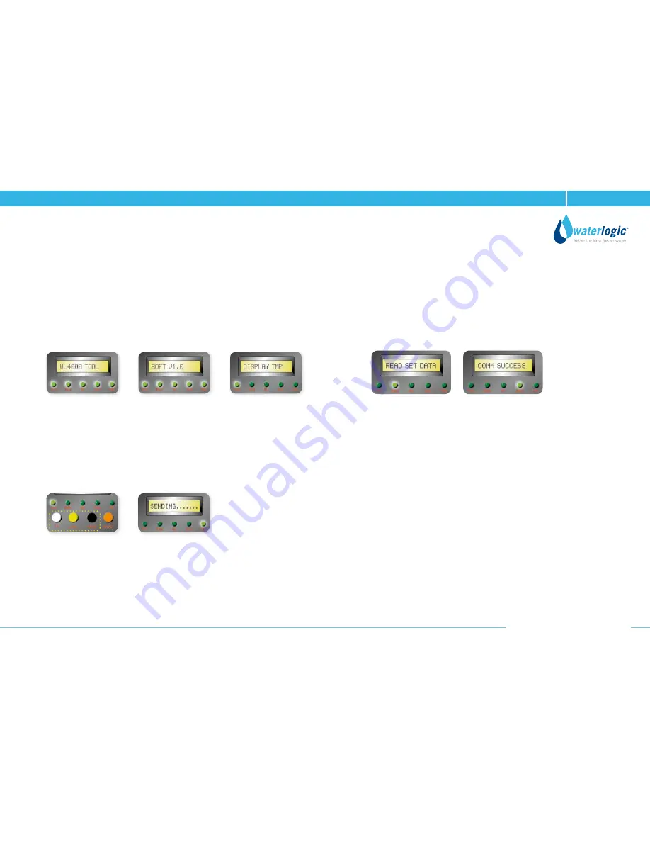
• Press the “Select” button and READ LED will illuminate.
The screen will show READ SET DATA.
Then press any of the three buttons (Up, Down or Enter) and screen display
will change to PRESS SEND KEY.
• Press the “Send” button, SENDING will show on the screen. This will be followed
by COMM SUCCESS which indicates that the Service PDCB is communicating
with the WL4 FIREWALL and reading the original setting data.
• Press the “Down” button to read whole PCB setting and press “Up” button
o read back from the top setting.
Note:
At this stage, the Service PCB can read the actual settings and cannot
change these settings.
Settings can be changed in the next step, Step 4.
STEP 2: INITIAL MODE & LCD DISPLAY
• When the Service PCB is p owered up it will display, in order, as below:
WL4 FIREWALL TOOL
SOFT V1.0 (Version)
DISPLAY TMP
• When the above display mode has finished, the word DISPLAY will appear
on the screen and only the green TEMP LED will remain illuminated.
• When the screen shows DISPLAY TMP and TEMP LED light is illuminated,
the current data information of the WL4 FIREWALL can be checked.
Cold Water Actual Temperature, Hot Water Actual Temperature and/or Filter
Timer as of now
• Press any one of the three buttons - Up, Down or Enter, the screen will show
Sending.
This shows the Service PCB is communicating with the WL4 FIREWALL to read
its actual data.
Содержание WL4 Firewall
Страница 1: ...WL4 Firewall Technical Manual...


