background image


WL350 Operating, Installation, and Service Manual                                                                       Page 6 – Revision 8-30-2016 


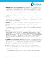
WARNING! 

CONNECT TO POTABLE WATER SUPPLY.  This system is to be used for water only and 

is not intended for use where water is microbiologically unsafe or with water of unknown quality 
without adequate disinfection. System is designed for the supplemental bactericidal treatment of 
public drinking water, or other drinking water, which has been tested and deemed acceptable for 
human consumption by the state or local health agency having jurisdiction.  The system is designed 
to reduce normally occurring non-pathogenic or nuisance microorganisms only.  System is not 
intended for treatment of contaminated water. 


WARNING!  

TIP HAZARD.  Dispenser could tip or fall causing serious injury.  Always install unit on a 

firm, flat, and level surface and secure the WL350 Water Treatment System to the base cabinet 
with the screw provided to lock the components together.  Secure unit to cabinet, wall, or floor if 
needed.  Never place heavy items on top of unit and never climb, stand, or hang on unit or storage 
cabinet to prevent injury and damage. 


WARNING!  

UNIT IS HEAVY.  TWO PERSON LIFT REQUIRED.  Transport unit empty and always use 

material handling equipment or two people with proper lifting technique to reduce injury risk. 


       WARNING!  

STORE AND TRANSPORT UNIT EMPTY. 


ALWAYS SANITIZE BEFORE USE. 

The unit must be completely drained and sealed before storing to avoid stagnation and reduce 
microbiological contamination (potential bacterial growth).  Sanitize before use to eliminate any 
potential microbiological contaminates


CAUTION!  

INDOOR USE ONLY.   Intended for household use only.  Never expose to direct sunlight, 

heat sources, or ambient air temperature above 37°C (100°F) or below 2°C (35°F).  Install indoors 
and keep unit away from excessive humidity.  Never expose to freezing temperatures.  Ensure 
there is adequate clearance around the unit to allow refrigeration system condenser to dissipate 
heat.  Warmer environments require more clearance around the unit.  Minimum clearance around 
all surfaces of the machine is 2-inches.  Installs where the ambient temperature exceeds 27°C 
(80°F), require a minimum of 4-inches clearance for proper heat dissipation and efficient 
operation.    


CAUTION!  

USE A WATER PRESSURE REGULATOR. Waterlogic will not be responsible for injury or 

damage caused by excessive water pressure.  Input or feed pressure must be 40 psi to 60 psi.  Be 
aware of any potential pressure surges caused by building/municipal pumping stations.  Water 
block devices and external leak detectors are strongly recommended. Locate the unit as close to 
the water supply and the electrical connections as possible to minimize risk.   


CAUTION!  

USE PROPER SUPPLY LINES AND FEED WITH POTABLE AMBIENT WATER ONLY. 

Feed water over 37°C (100°F) may damage the treatment components.  Always use supply lines 
with adequate pressure rating and UV resistance.  Close water supply valve and contact service 
representative if a leak is noticed.   


Contact Waterlogic for assistance or help finding an Authorized Service Representative.


Содержание WL350

Страница 1: ...aterlogic Commercial Products LLC 11710 Stonegate Circle Omaha NE 68164 800 288 1891 www waterlogic us Tech Portal Website www techportal waterlogic com WL350 OPERATING INSTALLATION AND SERVICE MANUAL...

Страница 2: ...Dealers employ trained service personnel who are experienced in the installation function and repair of Waterlogic equipment This publication is written for use by these qualified individuals Waterlo...

Страница 3: ...t Tank Descaling 18 Firewall Outlet Solenoid Reverse Flow Orientation 20 Adjusting Cold Water Set Point 21 Programming Disabling Energy Saving Sleep Mode 22 Programming Changing Hot Water Mode to Ambi...

Страница 4: ...perly grounded outlet Unit should be protected by ground fault circuit interrupter GFCI or residual current device RCD having a rated residual operating current not exceeding 30mA Use only Waterlogic...

Страница 5: ...ation and reduce microbiological contamination potential bacterial growth Sanitize before use to eliminate any potential microbiological contaminates CAUTION INDOOR USE ONLY Intended for household use...

Страница 6: ...ation and reduce microbiological contamination potential bacterial growth Sanitize before use to eliminate any potential microbiological contaminates CAUTION INDOOR USE ONLY Intended for household use...

Страница 7: ...essed Faucet 8 5 inch dispense height with BioCote recessed faucet to protect from cross contamination Leak Detection WL350 Water Treatment Systems are supplied with a Sensor in the Leak Tray that hal...

Страница 8: ...quirements are based on the recommendations of the U S Environmental Protection Agency s Task Force Report NSF ANSI 42 Chlorine Taste and Odor Reduction NSF ANSI 53 Lead and Cyst Reduction The Public...

Страница 9: ...d Water Temperature Cold Water Temperature Factory Set Point 5 C 41 F Adjustable to 1 1 12 2 C 34 54 F Hot Water Temperature 85 C 185 F Hot Water Manual Reset Overload 105 C 221 F Recommended Incoming...

Страница 10: ...13 5 x 14 5 x 41 Weight dry 26 3 kg 58 pounds 30 kg 66 pounds ELECTRICAL SPECIFICATIONS ELECTRICAL SUPPLY 120V 60Hz 15 Amp Service COMPONENT POWER approximate AMP DRAW approximate Heater 504 4 2 Amps...

Страница 11: ...ton within 3 seconds For Hot Water Press Hot Water Select Button followed by the Dispensing Button within 3 seconds NOTE Default selection mode is Cold Water Selection will return to default after 3 s...

Страница 12: ...tion to Waterlogic for evaluation The form is available at www waterlogic us Supporting documentation must include but is not limited to proof of purchase installation date failure date and supporting...

Страница 13: ...nect before removing UV Lamp CAUTION UV LAMPS ARE HAZARDOUS Lamps are considered Hazardous Waste and must be disposed of accordingly Refer to Product MSDS sheet for details 3 Clean the Spiral Quartz S...

Страница 14: ...in than out There is a small hole in the side of the tank outlet tube that allows air and water to pass into the vent chamber as it is heated Water in the vent chamber is suctioned back through the ou...

Страница 15: ...WL350 Operating Installation and Service Manual Page 15 Revision 8 30 2016 HEATER CIRCUIT HOT TANK WIRING...

Страница 16: ...ctive Metal Box on the rear of the hot tank As you look through the condenser coils on the rear of the unit you will see the hot tank located on the right hand side 5 From the front of the Water Treat...

Страница 17: ...y depressing the top flap of the Protective Metal Box so it snaps back into its original position on the Hot Tank 8 Replace the Lower Front Panel 9 Plug in the Power Cord 10 Turn on the Red Compressor...

Страница 18: ...NK DESCALING The Hot Tank is made from stainless steel Ensure descaling solution is compatible with stainless and always flush the unit completely Dispose in an environmentally safe manner Materials N...

Страница 19: ...customer s satisfaction WARNING HOT WATER The WL350 Water Treatment System produces Hot Water up to 86 C 187 F Water above 52 C 125 F can cause severe burns or scalding Hot water should be dispensed...

Страница 20: ...WL350 Operating Installation and Service Manual Page 20 Revision 8 30 2016 FIREWALL OUTLET SOLENOID REVERSE FLOW ORIENTATION...

Страница 21: ...erature and the range is approximately 7 C 20 F thru the full range of adjustment 7 00 to the 5 00 positions You should be able to turn the screw from the factory set point of 5 C 41 F 12 00 position...

Страница 22: ...r or longer period Selecting any button wakes up the WL350 Water Treatment System and turns the heater circuit back on The hot tank will typically take less than 10 minutes to heat the water from ambi...

Страница 23: ...t Cold settings On the Energy Saver PCB Move the Jumper on JP9 from Pins 1 and 2 to Pins 2 and 3 Unplug Power Cord and remove Top Cover to access Energy Saver PCB WL350 Water Treatment Systems comes w...

Страница 24: ...will determine proper filter type and maintenance schedule WLCP Part No FT 0063 One pre installed One required for NSF 53 and NSF P231 Certification Replacement parts can be obtained from Waterlogic o...

Страница 25: ...WL350 Operating Installation and Service Manual Page 25 Revision 8 30 2016 WL350 COUNTER TOP DRAWING AND PARTS LIST Wetted Parts...

Страница 26: ...ire EL 5053 Yes 3 1 EL 5010 Fuse 120V 15A 10 3013 Yes 4 EL 5004 Red Compressor Heater Switch 10 3008 Yes 5 ST 8216 Silver Back Panel Counter Top Only 12 8061 No 6 CT 2070 A Cold Tank Thermostat 19 106...

Страница 27: ...No 12 PL 1294 Leak Tray Counter Top Only 12 3155 Yes 13 ST 8151 A Bottom Tray Counter Top Only 12 3170 Yes 14 PL 1251 CN Unit Rubber Feet Counter Top Only 12 3150 Yes 15 PU 4010 JG Equal Straight Con...

Страница 28: ...3 Silicon Button Key Mat 12 8056 Yes 24 EN 6126 L00 00 Main PCB 12 8355 Yes 25 PL 1357 Firewall PCB Cover 12 8350 Yes 26 PL 1146 A Silver Front Panel for Drip Tray Insert Firewall 12 8345 Yes 27 PL 13...

Страница 29: ...0020 L00 00 Spiral Rubber Buffer Included in FU 0007 12 8305 Quartz Spiral Yes 36 FU 0008 A Firewall Mark IV Stainless Assembly No internal components includes FL 0010 Firewall Bracket 12 8330 Yes 36...

Страница 30: ...Tank 1 6 Liter 42 gallon 100V 500W Factory Set Point 185 F 85 C 12 5615 Yes 45 1 ST 8290 Thermostat and Overload Metal Cover 12 6900 Yes 45 2 HT 3012 Overload with Manual reset 105 C 221 F 12 1360 Ye...

Страница 31: ...1 AK 0014 B Flow Restrictor 1 8 mm hole AK 0014 B Yes 52 PU 4064 Silicon Tube 5 16 for Hot Water 10 7040 Yes 53 PU 4086 JG 1 4 Stopper PI0808S used with Bulkhead Union x John Guest P N PI1208S Counter...

Страница 32: ...WL350 Operating Installation and Service Manual Page 32 Revision 8 30 2016 WL350 TOWER LAYOUT DRAWING AND PARTS LIST Wetted Parts...

Страница 33: ...se 120V 15A with One Wire EL 5053 Yes 3 1 EL 5010 Fuse 120V 15A 10 3013 Yes 4 EL 5004 Red Compressor Heater Switch 10 3008 Yes 5 CT 2070 A Cold Tank Thermostat 19 1069 Yes 5 1 Lp 0326 l00 00 Cold Ther...

Страница 34: ...Wire Tower Only NA No 12 PL 1294 A Leak Tray Tower Only NA No 13 ST 8137 Bottom Tray 12 8004 Yes 14 ST 8167CN Unit Rubber Feet Tower Only 10 3083 Yes 15 PU 4137 JG 3 8 x 1 4 Reducing Fitting PI211208...

Страница 35: ...amp Assembly 12 8310 Yes 24 CT 2088 Firewall UV Lamp Rubber 12 8320 Yes 25 CT 2010 CDS Fixing Rubber Silicon 10 3095 Yes 26 FU 0007 Quartz Spiral 12 8305 Yes 27 FW 0020 L00 00 Spiral Rubber Buffer NA...

Страница 36: ...CT 2089 UV Sensor UVC Sensor Without Wire CT 2089 Yes 30 3 EL 5141 A Firewall UV Female Wire Connector 12 8335 Yes 31 PL 1351 Hot Water Faucet 12 8370 Yes 32 PL 1146 A Silver Front Panel for Drip Tray...

Страница 37: ...3 EN 6131 Energy Saver PCB 20 0075 Yes 44 HT 3041 Hot Tank 1 6 Liter 42 Gallon 100V 500W 12 5615 Yes 44 1 ST 8291 Thermostat and Overload Metal Cover 12 6900 Yes 44 2 HT 3012 Overload with Manual Rese...

Страница 38: ...1 4 John Guest P N PE 08 BI 1000F B Purchase from John Guest No 50 AK 0014 B Flow Restrictor 1 8 mm hole AK 0014 B Yes 51 PU 4064 Silicon Tube 5 16 for Hot Water 10 7040 Yes 52 CO 9027 Wire Condenser...

Страница 39: ...ervice Manual Page 39 Revision 8 30 2016 WL350 COUNTER TOP WATER FLOW DIAGRAM Cold Tank Filter Solenoid Valves Solenoid Valve Faucet Water Out Filter Dryer Compressor Condenser Hot Tank Water In Auxil...

Страница 40: ...vice Manual Page 40 Revision 8 30 2016 Inlet Leak Detection Valve WL350 TOWER WATER FLOW DIAGRAM Water Out Reverse Flow Cold Out Solenoid Valve Filter Water In Solenoid Valves Filter Dryer Condenser C...

Страница 41: ...on and Service Manual Page 41 Revision 8 30 2016 WL350 ELECTRICAL DIAGRAM DANGER HIGH VOLTAGE ELECTRICAL HAZARD PCB Printed Circuit Board contains High Voltage Only trained and qualified technicians s...

Страница 42: ...Systems and check exterior for damage Sanitizing Sanitize using a Household Bleach 5 25 Sodium Hypochlorite solution or other approved cleaner throughout the cold and sparkling water circuits Follow...

Страница 43: ...ilters to perform as represented and to provide the best quality water possible it is essential that filters be replaced periodically The frequency of filter changes depends upon your water quality an...

Страница 44: ...utes UV System Functional Test WARNING ULTRAVIOLET RADIATION Protect your skin and eyes against ultraviolet rays Never look directly at an operating UV light Disconnect wiring before removing 14 Remov...

Страница 45: ...ressor will shut off Draw a glass of cold water and verify it is has chilled to proper temperature Heater Test 22 Always ensure tanks are full of water before turning on the Heater or the Overload Hig...

Страница 46: ...to scalding hot water Disable Cold and Hot Tanks 1 Turn off the Red Heater and Compressor Power Switch O OFF to disable the Heater and Compressor 2 Dispense 2 liters gallon of water through the Hot Ta...

Страница 47: ...isable Cold and Hot Tanks 8 Turn off the Red Heater and Compressor Power Switch O OFF to disable the heater and compressor 9 Dispense 2 liters 1 gallon of water through the hot tank to cool the water...

Страница 48: ...ure above 37 C 100 F or below 2 C 35 F Install indoors and keep unit away from excessive humidity Never expose to freezing temperatures Ensure there is adequate clearance around the unit to allow refr...

Страница 49: ...dispensing button Hot tank is now full CAUTION NEVER TURN ON HEATER BEFORE FILLING HOT TANK Red Compressor Heater Switch must be in the O OFF position while the hot tank is empty Damage could occur wi...

Страница 50: ...has sensed water in the Leak Tray and will shut down inlet solenoid Possible Reason Solution Water is present in the Bottom Tray causing the leak detection to trigger Leak Detection is on the Counter...

Страница 51: ...t have adequate dose of UV Check UV System 1 If Ballast Indication Light is Green the system should be operational Ensure UV lamp is on Replace Lamp If lamp is replaced and problem persists replace UV...

Страница 52: ...and Service Manual Page 52 Revision 8 30 2016 FAULT CODE No LED Light Possible Reason Solution Power Problem Check for power disruption LED Light is out Check that the PCB LED is operational replace P...

Страница 53: ...ter and Compressor Power Switch won t light and the Red LED on the Front won t light Possible Reason Solution Circuit Breaker Check the Circuit Breaker Fuse is Blown Replace Fuse Defective Loose Power...

Страница 54: ...CB Replace Front PCB Defective Red Heater Compressor Switch Replace Red Heater Compressor Switch Compressor Runs But Does Not Chill Possible Reason Solution Condenser is dirty Clean the condensing coi...

Страница 55: ...position Turn Red Heater Compressor Switch on I ON Compressor Starting Circuit Turn Red Heater Compressor Switch off O OFF Remove the compressor cap on side of the compressor Disconnect the black and...

Страница 56: ...Hot Water coming out of Faucet Vent Hole 7 Restricted Flow of Hot Water 8 Hot Water Drip out of Faucet 9 Dispenses Hot and Cold Water at the same time 10 No cold water available 11 Water does not disp...

Страница 57: ...put water pressure is critical to the performance of the unit to allow solenoids to open Loose or bad connection on the Front Dispensing PCGB or Solenoid Connector Check that they are connected proper...

Страница 58: ...is filling the gap around the push buttons Inspect the push buttons and clean surrounding area Inspect faucet assembly inside the unit and clean as necessary Steady Drip Out of Faucet Possible Reason...

Страница 59: ...Tank outlet hole is scaled over Descale Tank See Hot Tank Descaling Instructions that are included further below in this Troubleshooting Section See instructional video on the Partner Area of the Wat...

Страница 60: ...the top to the Faucet The Hot Tank Outlet Tube has a Restrictor in its base This ensures the reservoir is always full by allowing more water in than out There is a small hole in the side of the Hot Ta...

Страница 61: ...pen the Water Supply Valve Cold Water Solenoid Valve malfunction Inspect the valve components for proper functionality Red Heater Compressor Switch on unit is off If water is dispensing at room temper...

Страница 62: ...Compressor Switch on I ON 15 Amp Fuse Blown Replace the 15 Amp Fuse as needed Water is present in the Bottom Tray causing the Leak Detection to trigger Remove the Top Cover and Front Panel Tip the uni...

Страница 63: ...tch the hot and cold wires on PCB red and blue connections If water now dispenses from the opposite side this is an indication that there is a PCB problem Replace PCB Solenoid If both the Water Pressu...

Страница 64: ...xed to the solenoid stem Remove the stem from the solenoid housing and allow water from the tank to flush out the contaminant s Dispense Buttons Stick Possible Reason Solution Dirt or Foreign material...

Страница 65: ...ry Waterlogic tank has an outlet restrictor to ensure the tanks remain full of water and water is controlled as it is released to the faucet The inlet solenoid controls flow into the tanks The tanks w...

Страница 66: ...K DESCALING The Hot Tank is made from stainless steel Ensure descaling solution is compatible with stainless and always flush the unit completely Dispose in an environmentally safe manner Materials Ne...

Страница 67: ...he customer s satisfaction WARNING HOT WATER The WL350 Water Treatment System produces Hot Water up to 87 C 187 F Water above 52 C 125 F can cause severe burns or scalding Hot water should be dispense...

Страница 68: ...quired Refrigerant has run out Run Compressor for at least ten minutes If Condenser is not warm then refill the refrigerant Compressor problem If Compressor is not running repair or replacement is nee...

Страница 69: ...ambient water to the 187 F set point Possible Reason Solution Is unit in Energy Star Sleep Mode If no water has been dispensed for 3 or more hours unit goes into sleep mode Dispense hot water wait 5...

Страница 70: ...ximately 26 OHM s resistance Hot Tank must be empty if you are checking for continuity Replace Hot Tank as necessary Loose or improperly connected wire s to the Heating Element Hot Tank Visually inspe...

Страница 71: ...eriod Selecting any button wakes up the WL350 Water Treatment System and turns the heater circuit back on The hot tank will typically take less than 10 minutes to heat the water from ambient to the 85...

Страница 72: ...ctive Metal Box on the rear of the hot tank As you look through the condenser coils on the rear of the unit you will see the hot tank located on the right hand side 5 From the front of the Water Treat...

Страница 73: ...y depressing the top flap of the Protective Metal Box so it snaps back into its original position on the Hot Tank 8 Replace the Lower Front Panel 9 Plug in the Power Cord 10 Turn on the Red Compressor...

Отзывы: