36
37
WL3000 Technical Manual - May 2014
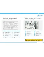
Electrical Wiring Diagram
Cold, Hot and Sparkling
Main PCB Schematic Diagram
Cold, Hot and Sparkling
A
230V from Red Switch
B
230V to UV Ballast
C
Output to UV Lamp
D
230V to Heater
E
230V from Green Switch
F
230V to Compressor
G
Level Probe
H
Cold Thermostat
I
Hot Thermostat
J
Not used
K
UV Sensor
L
Drip Tray Sensor
M
Not used
N
12 Pin Ribbon Cable
O
9 Pin Ribbon Cable
P
24V DC to Valve 5
Q
24V DC to Valve 4
R
24V DC to Valve 2
S
24V DC to Valve 1
T
24V DC to Pump
U
24V DC to Valve 3
V
24V DC IN from Transformer
W
230V DC to Transformer
X
Earth
Y
PCB Configuration
DANGER HIGH VOLTAGES PRESENT ON THIS PCB
CARE MUST BE TAKEN WHEN LIVE TESTING
Mark
Description
Mark
Description
20S1
Hot solenoid valve
PF
Power Fuse (250V/10A)
20S2
Cold solenoid valve
PS1
Control power switch
20S3
Sparkling solenoid valve
PS2
Comp & heater power switch
26H
Thermostat for overheat-hot tank Q 4 - 5
Transistor
BT
Ballast
RL 1-5
Relay
CDS
CDS for UNV Lamp
S 1 - 4
Temperature setting switch
CPU
Central processing unit + PCB
S
UV starter
DS
Drip tray sensor
T
Transformer for PCB
EF1
Enclosed fuse (1A)
TF
Internal thermal fuse
H
Hot water heater
TH1
Thermistor-hot water
MC
Motor for compressor
TH2
Thermistor-cold water
MFC
Motor for compressor IN
UV
UV lamp
P
Pump
WLVL
Sparkling water level check


