


WARNING
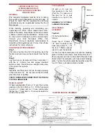
DO NOT OBSTRUCT FREE AIR SUPPLY TO THE
AIR INLET DUCT LOCATED AT THE BACK OF
THE STOVE.
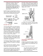
OUTSIDE AIR CONNECTION
This stove may be connected direct to the outside of
the house for its combustion air supply.
Note: It is recommended to use the shortest
possible outside air supply ducts. Supply ducts with
long runs, multi bends and corners may reduce air
volume supply due to excessive drag.
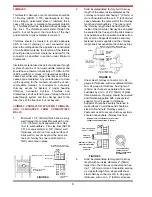
When connecting this stove to an outside air supply
the optional outside air kit must be used, which
includes a spigot, wire mesh, and fixing screws.
a.
Fit the cast iron spigot into the air inlet (Part
No. 39).
b.
Connect a 4” (100mm) stainless steel, gal
vanised ridge or flexible pipe to the air inlet
spigot.
c.
Fit a 4” (100mm) stainless steel or gal-
vanised sweep bend to the outside of the air
supply pipe.
d.
Fit the stainless mesh to the downturn of the
bend terminus using the fixing screws sup
plied with the outside air kit.
e.
Make sure that all joints are secured using
the fixing screws supplied with the outside
air kit.
f.
The outside air terminus must be fitted with
the 1/4” (6mm) x 1/4” (6mm) stainless wire
mesh to prevent leaves and rodents entering
from the out side.
g.
Air inlets traversing cavity walls should
include a continuous duct across the cavity.
The duct should be installed in such a man
ner as not to impair the weather resistance
of the cavity.
h.
Joints between air vents and outside walls
should be sealed to prevent ingress of mois
ture.
l.
This stove is listed for Mobile home installa
tion provided it is properly connected to an
outside air supply and a listed chimney with
a ceiling support and spark arrester.
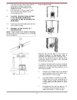
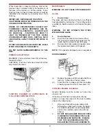
MOBILE HOME INSTALLATION
In addition to standard installation instructions the
following requirements are mandatory for installation
in a Mobile Home.
CAUTION: Do not obstruct combustion air opening.
1.
The stove must be permanently bolted to the
floor of the Mobile Home using the floor
screws provided.
2.
The stove must have a permanent outside
air source for combustion.
3.
The stove must be grounded to the steel
chassis of the Mobile Home.
4.
A listed chimney system, roof thimble, spark
arrestor and roof flashing kit suitable for use
in Mobile Homes must be used.
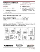
5.
If the chimney exits the Mobile Home at a
location other than through the roof, and
exits at a point 7ft. (2100mm) or less above
the ground level on which the Mobile Home
is positioned, a guard or method of enclosing
the chimney shall be fitted at the point of exit
for a height up to 7 ft.(2100mm).
6.
The chimney shall be attached directly to the
room heater and shall extend at least 3 ft.
(910mm) above the part of the roof through
which it passes. The top of the chimney
should project at least 2 ft. (610mm) above
the highest elevation of any part of the
Mobile Home within 10 ft. (3050mm) of the
chimney.
4
DO NOT CONNECT TO OR USE IN CONJUNC-
TION WITH ANYAIR DISTRIBUTION DUCTWORK
UNLESS SPECIFICALLY APPROVED FOR SUCH
INSTALLATIONS.